
WLD-210 · Lesson 8 of 12 · 17 min
Setting voltage, wire feed speed and stickout
Every wire weld comes down to a handful of variables: wire feed speed, voltage, contact tip to work distance, travel speed, gun angles and, behind them all, the wire and gas. They interact. Change the stickout and the current changes; change the voltage and the bead shape and transfer mode change; change the travel speed and the bead size and heat input change. Marta Kowalchuk's goal for Devon this week is to understand each knob well enough to set up any procedure from the numbers on the sheet, check it with a meter and a stopwatch, and correct it from what he sees in the bead. This lesson treats each variable in turn, then puts them together into deposition rate, efficiency and a setup routine.
Wire feed speed and current
On a constant-voltage machine, the welder does not set the current directly. The wire is fed at a set speed, and the arc draws whatever current is needed to melt it at that rate. Faster wire means more current. For a given wire, the relationship between wire feed speed and current is nearly fixed, so wire speed is the most reliable number to put in a procedure: it can be measured directly by running the wire into a measured length for a timed interval, and it does not drift with cable length or meter accuracy the way current readings can.
The relationship is not perfectly fixed, because the wire is heated in two ways on its way to the arc. The arc heats the tip. And the current flowing through the length of wire between the contact tip and the arc, the electrical stickout, heats the wire by its own resistance, just as current heats the element of a toaster. That resistance heating grows with the square of the current and with the length of stickout. Increase the stickout and the wire arrives at the arc already hot, so less current from the arc is needed to melt it: at the same wire speed, the current falls. Flux-cored and metal-cored wires have a thinner steel sheath carrying all the current, so they heat more in the stickout than solid wires of the same diameter.
The melting rate of the wire is often written as two terms: one proportional to the current, for the arc heating at the tip, and one proportional to the stickout length times the current squared, for the resistance heating. The coefficients depend on the wire, and the numbers in the code below are illustrative.
# Current needed to melt a wire at a set speed, at different stickouts (illustrative melt-rate model)
import math
alpha = 0.3        # arc melting term, mm3 per second per amp
beta = 9e-05         # resistance heating term, mm3 per second per (mm x A^2)
area = math.pi * 1.2 ** 2 / 4
wfs = 8.0         # wire feed speed, m/min
melt_needed = area * wfs * 1000 / 60          # wire volume to melt per second
for stickout in (15, 20, 25, 30):
    # solve alpha*I + beta*L*I^2 = melt_needed for I
    a, b, c = beta * stickout, alpha, -melt_needed
    amps = (-b + math.sqrt(b * b - 4 * a * c)) / (2 * a)
print(f"stickout {stickout:5} mm -> about {amps:4.0f} A at {wfs} m/min")stickout 15 mm -> about 241 A at 8.0 m/min stickout 20 mm -> about 218 A at 8.0 m/min stickout 25 mm -> about 201 A at 8.0 m/min stickout 30 mm -> about 187 A at 8.0 m/min
Doubling the stickout drops the current noticeably at the same wire speed. That means a welder who holds the gun farther away to see the joint is turning down the heat without touching the machine, and one who drifts in and out is welding with a constantly changing current. It also explains why procedures for flux-cored and metal-cored wires give a stickout range and why Lucia checks it.
Contact tip to work distance, stickout and arc length
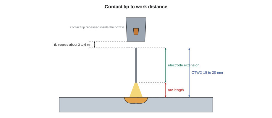
Three distances are easy to confuse. The contact tip to work distance, CTWD, is from the end of the contact tip to the work surface. The electrode extension or stickout is the length of wire from the contact tip to the start of the arc. The arc length is the gap from the wire tip to the pool. CTWD is the sum of the stickout and the arc length, and it is the one a welder can see and measure. Procedures usually specify CTWD or electrode extension in a range, for example 15 to 20 mm (5/8 to 3/4 in) for spray and gas-shielded flux-cored wire, 6 to 12 mm (1/4 to 1/2 in) for short-circuit, and longer, up to 25 to 50 mm (1 to 2 in) or more, for some self-shielded wires that rely on resistance preheating to work correctly.
Voltage
Voltage sets the arc length. Within the right range for the transfer mode, a higher voltage gives a longer, wider arc, a flatter, wider bead with better wetting at the toes, and slightly less penetration in the middle; a lower voltage gives a shorter, more concentrated arc, a narrower, more crowned bead and, at the extreme, stubbing. Outside the range, too high a voltage causes undercut, porosity from the longer arc pulling in air, and in short-circuit work a change toward globular transfer; too low gives a ropey, convex bead with poor tie-in at the toes and, in short-circuit, stubbing and lack of fusion. Voltage must rise with wire speed: a higher current needs a longer arc to stay in the same transfer mode.
Two common faults in setup come from treating voltage as a heat control. Turning up the voltage on a short-circuit arc to get more penetration does not add much heat; it lengthens the arc and makes spatter. And turning down the voltage on a spray arc to narrow the bead can drop it into globular or short-circuit transfer. The rule of thumb Marta gives Devon: wire speed for heat and metal, voltage for arc length and bead shape.
Travel speed and gun angles
Travel speed sets the bead size and, with current and voltage, the heat input. Too slow, and the pool gets ahead of the arc and the bead becomes large and convex, with the risk of cold lap and excess heat input. Too fast, and the bead is narrow and peaked, with undercut and incomplete fusion at the toes. The right travel speed keeps the arc on the leading edge of the pool and makes a bead of the size the procedure calls for.
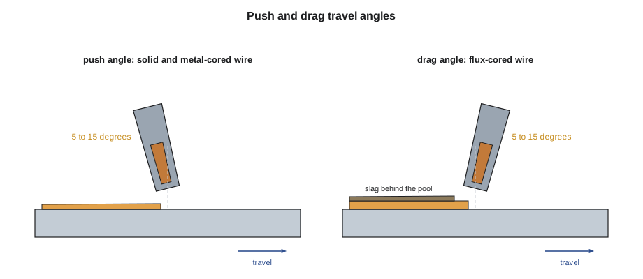
Gun angles are named like stick electrode angles. The work angle is the angle between the gun and the plate surface, seen along the joint: about 45 degrees for a flat fillet, lowered toward the horizontal plate for a horizontal fillet, and split evenly for a groove. The travel angle is the lean of the gun along the weld. Pointing the gun ahead, in the direction of travel, is a push or forehand angle; pointing it back toward the finished weld is a drag, pull or backhand angle.
- A push angle of about 5 to 15 degrees gives a flatter, wider bead, better gas coverage and a clear view of the joint. It is normal for solid and metal-cored wire.
- A drag angle of about 5 to 15 degrees gives deeper penetration and a narrower, higher bead, and keeps the slag behind the pool. It is normal for flux-cored wire. The shop saying is: if there is slag, drag.
- Angles beyond about 20 degrees either way blow air into the shield and make an erratic arc.
Deposition rate and efficiency
How much weld metal does a setting put in the joint? The melting rate is the mass of wire melted per hour, which is simply the wire feed speed times the mass of wire per unit length. Not all of it ends up in the weld. Some is lost as spatter and fume, and for flux-cored wire some of the core becomes slag rather than metal. The deposition efficiency is the fraction of the wire mass that becomes weld metal, and the deposition rate is the melting rate times that efficiency.
Here v_w is the wire feed speed per minute, m_w the mass of wire per unit length and η_d the deposition efficiency. Typical deposition efficiencies are about 95 to 98 percent for solid wire in spray or pulse, 90 to 95 percent in short-circuit, 92 to 96 percent for metal-cored wire, 82 to 90 percent for gas-shielded flux-cored wire and 78 to 85 percent for self-shielded wire, compared with about 60 to 70 percent for stick electrodes once the stub and coating are counted. Wire makers publish deposition rate charts, and the wire's data sheet gives its mass per length.
# Melting rate, deposition rate and spatter and slag loss for one setting
wires = [  # name, mass per m (g), deposition efficiency
    ("solid wire, spray", 8.9, 0.97),
    ("gas-shielded flux-cored", 7.4, 0.86),
    ("metal-cored", 8.0, 0.95),
]
wfs = 8.0         # wire feed speed, m/min
for name, m, eff in wires:
    melt = wfs * m * 60 / 1000              # kg/h melted per arc hour
    dep = melt * eff
print(f"{name:25} melts {melt:4.1f} kg/h, deposits {dep:4.1f} kg/h, loses {melt - dep:3.1f} kg/h")solid wire, spray melts 4.3 kg/h, deposits 4.1 kg/h, loses 0.1 kg/h gas-shielded flux-cored melts 3.6 kg/h, deposits 3.1 kg/h, loses 0.5 kg/h metal-cored melts 3.8 kg/h, deposits 3.6 kg/h, loses 0.2 kg/h
At the same wire speed, a flux-cored wire melts less steel than a solid wire, because its core is lighter than steel, and loses more of it to slag. But flux-cored wire can usually run at a higher current and wire speed in a given position, which is why it still out-deposits solid wire on vertical and overhead plate work.
Spatter
Spatter is metal lost from the arc. It costs wire, it costs the grinding time to remove it, and it can clog nozzles and cause gas problems. It comes mainly from violent short circuits, globular drops, wrong voltage, long arcs, contaminated plate and incorrect polarity. Spray, pulse and well-set flux-cored arcs spatter little. Anti-spatter sprays on the plate help with cleanup on visible work, but on welds that will be painted or galvanized some sprays must be avoided or removed, and Lucia checks the job specification before they are used.
From the procedure to the arc
Hartwell's welding procedures give, for each pass: wire classification and diameter, gas and flow, polarity, wire feed speed, current range, voltage range, CTWD, travel speed range and, where needed, heat input limits and transfer mode or program. Devon's setup routine:
- Set the wire feed speed from the procedure, and check it by running wire for 6 seconds into a clean bucket and measuring the length: 6 seconds times 10 gives the length per minute.
- Set the voltage, and run a test bead on scrap of the same thickness.
- Measure current with a clamp meter on the work lead and voltage across the gun and work, or read them from a calibrated machine display, while welding.
- Time a measured length of bead to get travel speed and calculate heat input if the procedure limits it.
- Adjust voltage for bead shape within the procedure range, and record the final settings.
# Check a test bead against a procedure: wire speed, volts, amps, travel and heat input
wps = {"wfs": (7.0, 9.5), "volts": (24, 28), "amps": (220, 270), "travel": (300, 450), "q_max": 1.5}
test = {"wire_in_6s": 0.84, "volts": 26.5, "amps": 248, "length": 300, "seconds": 52}
wfs = test["wire_in_6s"] * 10                       # m/min
travel = test["length"] / test["seconds"] * 60      # mm/min
q = 60 * test["volts"] * test["amps"] / (1000 * travel)
checks = {
    "wire speed": wps["wfs"][0] <= wfs <= wps["wfs"][1],
    "voltage": wps["volts"][0] <= test["volts"] <= wps["volts"][1],
    "current": wps["amps"][0] <= test["amps"] <= wps["amps"][1],
    "travel speed": wps["travel"][0] <= travel <= wps["travel"][1],
    "heat input": q <= wps["q_max"],
}
print(f"wire speed {wfs:.1f} m/min, travel {travel:.0f} mm/min, heat input {q:.2f} kJ/mm")
for name, ok in checks.items():
print(f" {name:13} {'OK' if ok else 'OUT OF RANGE'}")wire speed 8.4 m/min, travel 346 mm/min, heat input 1.14 kJ/mm wire speed OK voltage OK current OK travel speed OK heat input OK
Reading the bead
| What the bead shows | Likely cause | Correction |
|---|---|---|
| Narrow, ropey, convex, poor toes | Voltage low or travel fast | Raise voltage or slow travel |
| Wide, flat, undercut at toes | Voltage high or travel slow on a thin plate | Lower voltage or raise travel speed |
| Heavy spatter, irregular arc | Voltage wrong for mode, long stickout, wrong polarity | Reset voltage, hold CTWD, check polarity |
| Large, rolled-over bead | Travel too slow; pool ahead of arc | Speed up, keep arc on leading edge |
| Surface pores or grey, sooty bead | Poor gas coverage, drafts, angle too steep | Check flow, screens, nozzle, angle |
| Wormholes in flux-cored welds | Stickout too long or short, damp wire, low voltage | Hold CTWD, check wire storage and settings |
Common mistakes
MistakePulling the gun back to see better without thinking about the current.
InsteadLonger stickout lowers the current at the same wire speed.
MistakeUsing voltage to add heat.
InsteadWire speed adds heat; voltage sets arc length.
MistakePushing a flux-cored wire because solid wire is pushed.
InsteadDrag flux-cored wire so slag stays behind the pool.
MistakeTrusting the dial instead of measuring wire speed.
InsteadRun wire for six seconds and measure it.
MistakeIgnoring deposition efficiency when estimating wire.
InsteadAllow for spatter, fume and slag losses.
Summary and key terms
- Wire feed speed sets current; stickout changes current at a set wire speed through resistance heating.
- CTWD is stickout plus arc length and is specified in the procedure.
- Voltage sets arc length and bead shape and must rise with wire speed to stay in the same mode.
- Travel speed sets bead size and heat input; the arc must stay on the leading edge of the pool.
- Push solid and metal-cored wire; drag flux-cored wire.
- Deposition rate equals melting rate times deposition efficiency.
- Settings are checked by measuring wire speed, voltage, current and travel speed on a test bead.
- Contact tip to work distance
- The distance from the end of the contact tip to the work surface.
- Electrode extension
- The length of wire between the contact tip and the arc, also called stickout.
- Resistance heating
- Heating of the wire extension by the welding current flowing through it.
- Push angle
- A travel angle with the gun pointing in the direction of travel.
- Drag angle
- A travel angle with the gun pointing back toward the finished weld.
- Melting rate
- The mass of wire melted per unit time.
- Deposition efficiency
- The fraction of melted wire that becomes weld metal.
Practice problems
Work each problem on paper first, then reveal the answer to check.
Wire run for 6 s measures 0.78 m. What is the wire feed speed?
Show answer
0.78 × 10 = 7.8 m/min.
A 1.2 mm wire weighs 8.9 g/m and feeds at 9 m/min with 0.96 efficiency. What is the deposition rate?
Show answer
9 × 8.9 × 60 × 0.96 / 1000 ≈ 4.6 kg/h.
A welder lengthens the stickout at the same wire speed. What happens to the current?
Show answer
It falls.
Lesson quiz · 5 questions
Score 60% or more to complete this lesson.
Create a free account to save your progress, take quizzes and earn a certificate.