
WLD-210 · Lesson 12 of 12 · 21 min
Capstone: qualifying a production FCAW procedure on the bridge girder
The Riverside pedestrian bridge has two weathering steel plate girders about 36 m (118 ft) long, too long to ship in one piece from Hartwell's bay to the river crossing. Each girder is built in three shop pieces, and the flanges of each piece are made from plates joined end to end by complete joint penetration butt welds, called shop splices, before the girder is assembled. Those flange splices are among the most critical welds on the bridge: the bottom flange is in tension under every footstep, and a defect in a flange butt weld is the kind of thing that grows by fatigue. The bridge specification calls for the flange splices to be welded with gas-shielded flux-cored wire under a procedure qualified by test, with the weld metal tested for strength, ductility and toughness. This capstone follows the qualification from the plan to the first production weld. Glen Teskey assigns it to Marta Kowalchuk as welder, Lucia Ferreira as inspector and Hartwell's welding engineer, Elena Marchetti, as the engineer responsible for the procedure. Devon Okafor keeps the records, and the job becomes his first look at how a welding procedure is born.
Step 1: Read the requirements
Elena starts by listing what the documents require. The drawings show the flange splices as double-V complete joint penetration groove welds, back-gouged, in flanges 25 mm (1 in) and 40 mm (1-1/2 in) thick, ground flush after welding and tested by ultrasonic testing. The specification and the code set the rest:
The bridge is designed to CSA S6, the Canadian Highway Bridge Design Code, which calls for welding to CSA W59 by a fabricator certified to CSA W47.1, and for weld metal toughness suitable for the bridge's minimum service temperature. Hartwell holds W47.1 certification. Its welding procedure specification and welding procedure data sheets must be accepted by the Canadian Welding Bureau, and because the specification requires the flux-cored procedure for the flange splices to be qualified by test with Charpy testing of the weld metal, the test plate is welded in front of a CWB representative and the specimens are tested by a laboratory. The job specification asks for an average of at least 27 J at −30 °C from the weld metal Charpy tests, with no single value below 20 J, figures used here for illustration.
Both codes also limit the wire's diffusible hydrogen, so the wire must carry an H8 or lower designator, and they require that the procedure stay within the limits on heat input, preheat and interpass temperature that were tested. Elena's note to the team is short: we will qualify one procedure, carefully, and then weld every splice exactly as we tested.
Step 2: Choose the variables
Elena chooses the procedure variables so the qualified ranges will cover the production work without being so wide that any one weld is far from what was tested:
| Variable | Chosen for the test |
|---|---|
| Process | FCAW-G, semi-automatic |
| Wire | E491T1-M21A4-CS1-H8, 1.2 mm, one brand and trade name |
| Gas | Argon with 25 % carbon dioxide (M21), 20 L/min |
| Polarity | DCEP |
| Base metal | CSA G40.21 350AT weathering steel, 25 mm test plate |
| Joint | Double-V groove, 60 degree included angle, 3 mm root face, 0 to 3 mm root opening, back-gouged |
| Position | Flat (1G); production splices are welded flat on the turning rolls |
| Electrical | 235 to 255 A, 25.5 to 26.5 V, CTWD 19 mm |
| Technique | Stringer and split-layer passes, no weave wider than the procedure limit, drag 5 to 10 degrees |
| Preheat and interpass | Minimum 20 °C, maximum interpass 230 °C |
| Heat input | Target 1.4 to 1.8 kJ/mm, recorded per pass |
The wire is a gas-shielded rutile wire with improved toughness. Weathering steel would normally call for a weathering-grade wire for exposed multipass welds, but the flange splices are ground flush and the specification accepts the matching-strength carbon steel wire for these welds, because the weld surface is small and the girders' exposed welds elsewhere use a nickel-bearing wire. Elena records the reason in the procedure file so the question does not come up again during the inspection.
Step 3: The first test plate
Marta welds the first test plate on a Tuesday morning, with the CWB representative present, as the code requires. Devon records each pass on a log sheet: pass number, side, wire speed, current and voltage from a calibrated meter, the length of each pass and its time, and the interpass temperature measured with a contact thermometer before each pass. After side A is complete, the plate is turned, the root is back-gouged with air carbon arc gouging, ground bright, and checked by magnetic particle testing, and side B is welded.
The plate looks good, but the radiograph shot before mechanical testing shows a slag line about 20 mm (3/4 in) long along the sidewall between the fifth pass and the bevel on side A. Lucia rejects the plate. Marta looks at the log and her own memory together: on the fifth pass, the groove had widened, and she had run one wide weave across it at the top of the current range to save a pass. The slag ran ahead of the arc at the sidewall and was trapped. Elena changes one thing in the technique: from the fourth layer up, layers are split into two stringers, each aimed at its own sidewall. The written procedure already limits weave width; the test shows that the limit is real.
Devon asks whether the failed plate is wasted. Elena's answer is no: it is evidence that the technique matters, and it is the reason the production procedure will say split layers in plain words, with a sketch, not just a maximum bead width in a table.
Step 4: The second test plate
The second plate is welded on Thursday with split layers above the third pass. Devon's log shows nine passes, six on side A and three on side B after back-gouging, all within the planned ranges.
# Step 4: pass log from the second test plate, heat input per pass and interpass check
passes = [  # pass, side, volts, amps, length mm, seconds, interpass before the pass (C)
    (1, "A", 24.5, 205, 400, 110, 22), (2, "A", 25.5, 235, 400, 98, 95), (3, "A", 26.0, 245, 400, 92, 140),
    (4, "A", 26.0, 250, 400, 96, 165), (5, "A", 26.0, 250, 400, 94, 180), (6, "A", 26.5, 255, 400, 92, 190),
    (7, "B", 25.5, 235, 400, 102, 60), (8, "B", 26.0, 250, 400, 94, 150), (9, "B", 26.0, 250, 400, 93, 175),
]
preheat_min, interpass_max = 20, 230
q_list = []
for p, side, v, a, length, sec, tip in passes:
    speed = length / sec * 60
    q = 60 * v * a / (1000 * speed)
    q_list.append(q)
    ok = preheat_min <= tip <= interpass_max
    print(f"pass {p} side {side}: {speed:5.0f} mm/min  {q:4.2f} kJ/mm  interpass {tip:3} C {'ok' if ok else 'OUT'}")
print(f"heat input range {min(q_list):.2f} to {max(q_list):.2f} kJ/mm")pass 1 side A: 218 mm/min 1.38 kJ/mm interpass 22 C ok pass 2 side A: 245 mm/min 1.47 kJ/mm interpass 95 C ok pass 3 side A: 261 mm/min 1.47 kJ/mm interpass 140 C ok pass 4 side A: 250 mm/min 1.56 kJ/mm interpass 165 C ok pass 5 side A: 255 mm/min 1.53 kJ/mm interpass 180 C ok pass 6 side A: 261 mm/min 1.55 kJ/mm interpass 190 C ok pass 7 side B: 235 mm/min 1.53 kJ/mm interpass 60 C ok pass 8 side B: 255 mm/min 1.53 kJ/mm interpass 150 C ok pass 9 side B: 258 mm/min 1.51 kJ/mm interpass 175 C ok heat input range 1.38 to 1.56 kJ/mm
The root pass on side A has the lowest heat input, because it is run at the bottom of the current range for good control at the root; the fill passes are higher. The interpass temperature climbs pass by pass but stays well below the maximum, because the plate is large and Marta lets it cool slightly between passes. The radiograph and the ultrasonic test of the second plate are clean.
Step 5: Cut and test the specimens
The laboratory cuts the test plate according to the code's layout: reduced-section tensile specimens across the weld, side bend specimens across the weld, an all-weld-metal tensile specimen and a set of Charpy V-notch specimens with the notch in the weld metal, and a macro-etch section. Lucia marks the cut lines on the plate and photographs it before it goes, so that every specimen can be traced to its place in the weld.
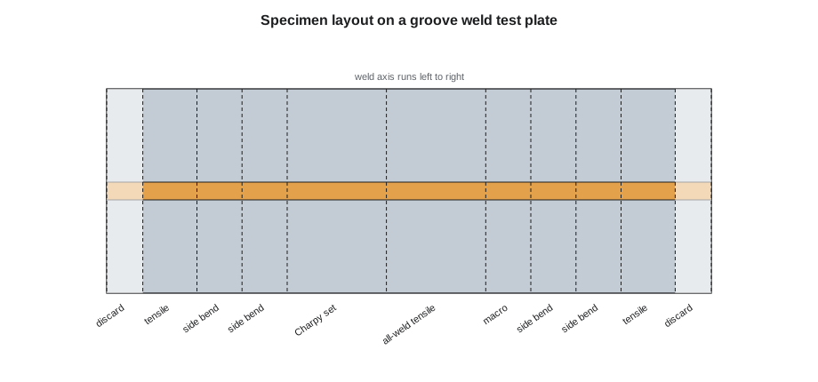
The specimens test different things:
- Reduced-section tensile specimens pull the joint until it breaks and show that the welded joint is at least as strong as the plate's specified minimum tensile strength.
- Side bend specimens bend a slice of the full thickness around a mandrel, stretching the weld cross-section, and show ductility and freedom from lack of fusion and slag.
- The all-weld-metal tensile specimen, machined from the weld itself, measures the weld metal's own yield, tensile strength and elongation.
- Charpy specimens measure the weld metal's toughness at the test temperature.
- The macro etch shows the passes, the fusion into both bevels and the absence of root defects.
Step 6: Evaluate the results
The laboratory report comes back a week later. Devon checks it against the requirements with Elena.
# Step 6: evaluate the mechanical test results against the job requirements
req = {"tensile_min": 480, "bend_open_max": 3.0, "cvn_avg_min": 27, "cvn_single_min": 20}
tensile = [566, 572]                 # reduced-section tensile, MPa (break location noted)
bends = [0.0, 0.0, 1.5, 0.0]          # side bends, largest opening, mm
cvn = [61, 74, 58, 69, 47]     # weld metal Charpy at -30 C, J
results = {
    "tensile": all(t >= req["tensile_min"] for t in tensile),
    "side bends": all(b <= req["bend_open_max"] for b in bends),
}
cv = sorted(cvn)[1:-1]                 # drop highest and lowest of five, average the middle three
avg = sum(cv) / 3
results["Charpy average"] = avg >= req["cvn_avg_min"]
results["Charpy single"] = min(cvn) >= req["cvn_single_min"]
print(f"tensile {tensile} MPa vs minimum {req['tensile_min']}")
print(f"bends largest opening {max(bends)} mm vs {req['bend_open_max']}")
print(f"Charpy {cvn} J: average of middle three {avg:.0f}, lowest {min(cvn)}")
for k, ok in results.items():
    print(f"  {k:15} {'pass' if ok else 'FAIL'}")
print("PQR result:", "acceptable" if all(results.values()) else "not acceptable")tensile [566, 572] MPa vs minimum 480 bends largest opening 1.5 mm vs 3.0 Charpy [61, 74, 58, 69, 47] J: average of middle three 63, lowest 47 tensile pass side bends pass Charpy average pass Charpy single pass PQR result: acceptable
Both tensile specimens broke in the plate away from the weld, the best possible result. One side bend showed a small opening, within the limit; the others were clean. The Charpy values have the usual scatter, and the lowest specimen came from near the cap, where the last pass had no later pass to refine its grains, but it is well above the single-value minimum. The all-weld-metal tensile test showed yield and tensile strengths above the wire's classification minimums with good elongation, and the macro showed full fusion and the back-gouged root cleanly consumed. Elena signs the procedure qualification record, the PQR. In Canada, the record goes to the CWB for acceptance with the welding procedure data sheet; in the United States, it goes to the engineer with the WPS for approval.
Step 7: Write the production procedure
The PQR records what was done on one plate on one day. The WPS is the instruction for production, written with ranges around those values. The code sets the limits within which each variable can move without requalification: changes in the wire classification, the gas, the polarity or the position, or increases in heat input beyond what was tested, can all need a new test, while small changes in current, voltage and travel speed are allowed within set percentages. Hartwell's welding engineer sets the production ranges inside the code limits, and tighter than them where experience says to.
# Step 7: production ranges from the qualified values (illustrative limits set by Hartwell's welding engineer)
pqr = {"amps": 250, "volts": 26.0, "travel": 255, "q_max": 1.8, "preheat": 20, "interpass": 230}
limits = {"amps": 0.10, "volts": 0.07, "travel": 0.25}
wps = {k: (round(pqr[k] * (1 - f), 1), round(pqr[k] * (1 + f), 1)) for k, f in limits.items()}
for k, (lo, hi) in wps.items():
    print(f"{k:7} {lo} to {hi}")
print(f"heat input not above {pqr['q_max']} kJ/mm; preheat at least {pqr['preheat']} C; interpass not above {pqr['interpass']} C")
# first production check on girder G1, top flange splice, side A, fill passes
checks = [(262, 26.8, 260), (281, 26.2, 255), (248, 25.4, 190)]
for amps, volts, travel in checks:
    q = 60 * volts * amps / (1000 * travel)
    bad = [k for k, val in (("amps", amps), ("volts", volts), ("travel", travel)) if not wps[k][0] <= val <= wps[k][1]]
    if q > pqr["q_max"]:
        bad.append("heat input")
print(f"{amps} A {volts} V {travel} mm/min -> {q:.2f} kJ/mm " + ("OK" if not bad else "outside: " + ", ".join(bad)))amps 225.0 to 275.0 volts 24.2 to 27.8 travel 191.2 to 318.8 heat input not above 1.8 kJ/mm; preheat at least 20 C; interpass not above 230 C 262 A 26.8 V 260 mm/min -> 1.62 kJ/mm OK 281 A 26.2 V 255 mm/min -> 1.73 kJ/mm outside: amps 248 A 25.4 V 190 mm/min -> 1.99 kJ/mm outside: travel, heat input
Lucia's first production check on girder G1 catches a problem on the third pass she watches: the welder slowed down to fill a low spot, the travel speed dropped below the range and the heat input went over the qualified maximum. The weld is not automatically rejected; Elena reviews the length involved, the welder is reminded of the split-layer rule, and the event is recorded. The second pass she watched shows another lesson: 281 A is just outside the current range even though the heat input is fine, because the welder had turned up the wire speed. The WPS is a set of limits, not a target, and every variable must be inside them at once.
The final WPS for the flange splices fits on two pages: the joint sketch with tolerances; the wire by classification, size, brand and trade name; the gas and flow; polarity; the pass sequence with a sketch showing split layers from the fourth layer up and the back-gouge; current, voltage, wire speed, CTWD and travel speed ranges; heat input maximum; preheat and interpass temperatures; cleaning between passes; and the inspection hold points. A copy is posted at the splice station in a plastic sleeve.
Step 8: Qualify the welders
A qualified procedure is not enough; every welder who makes the splices must be qualified for the process, the position and the thickness. Marta's earlier qualification on the same process covers her. Two other welders take their groove tests with flux-cored wire on backing, as do the welders for the stiffener fillets. Devon takes his first flux-cored groove tests in the vertical and overhead positions on 10 mm (3/8 in) plate, the tests he has practised for since the last lesson, and both sets of bend specimens pass. He is now qualified for flux-cored groove and fillet welds in all positions within his test's thickness range, for production work under supervision. He will not weld the flange splices yet: the shop's rule is that bridge main member welds go to welders with a year of production flux-cored work. But he can weld the stiffener fillets, under the qualified procedure for those.
# Step 8: welder qualification check before a welder is assigned to a weld
welders = {
    "Marta": {"process": "FCAW-G", "groove_positions": {"1G", "2G", "3G", "4G"}, "max_thk": 999, "months_fcaw": 120},
    "Devon": {"process": "FCAW-G", "groove_positions": {"1G", "2G", "3G", "4G"}, "max_thk": 20, "months_fcaw": 1},
}
def can_weld(name, weld, rule_months=12):
    w = welders[name]
    reasons = []
    if w["process"] != weld["process"]:
        reasons.append("process")
    if weld["position"] not in w["groove_positions"]:
        reasons.append("position")
    if weld["thickness"] > w["max_thk"]:
        reasons.append("thickness")
    if weld.get("main_member") and w["months_fcaw"] < rule_months:
        reasons.append("shop rule: one year of production FCAW for main member splices")
    return "yes" if not reasons else "no (" + ", ".join(reasons) + ")"
splice = {"process": "FCAW-G", "position": "1G", "thickness": 40, "main_member": True}
stiffener = {"process": "FCAW-G", "position": "1G", "thickness": 16, "main_member": False}
for n in welders:
print(f"{n}: flange splice {can_weld(n, splice)}; stiffener fillets {can_weld(n, stiffener)}")Marta: flange splice yes; stiffener fillets yes Devon: flange splice no (thickness, shop rule: one year of production FCAW for main member splices); stiffener fillets yes
Step 9: Production and inspection
The production splices follow the WPS exactly. At each splice, Lucia checks the fit-up and preheat before welding, watches the root and the first fill passes, checks the back-gouge with magnetic particle testing, and checks the finished weld visually before grinding. After the flanges are ground flush, every splice is tested ultrasonically by Hartwell's NDT technician, and the reports go into the girder's quality file with the PQR, WPS, welder qualifications, wire certificates and the pass logs. When the bridge inspector from the owner visits the shop, the file answers each question before it is asked: which wire, which welder, which procedure, which test.
One splice of the twelve shows a small indication near the root on ultrasonic testing. It is excavated, found to be a small slag pocket from the back-gouge, repaired under the shop's repair procedure and retested clean. The repair is recorded with the splice. Twelve splices with one repair is an acceptable rate; Lucia tracks it, because if it rose, the first suspect would be the back-gouging and grinding, not the procedure.
What Devon takes away
Devon's last notebook page for the course lists what the capstone tied together: the equipment and the cable voltage drop that made the meter checks matter; the wire classification that had to match the procedure field by field; the gas and its group; the transfer mode and its limits; the settings and how stickout changes current; heat input calculated per pass; the slag behaviour of a T1 wire and why a wide weave trapped slag; split layers and cleaning between passes; and the difference between a PQR, which records one test, and a WPS, which governs every weld after it. At the bottom he writes the line Marta repeats most often: the procedure was qualified once, but it has to be followed every time.
Common mistakes
MistakeTreating the WPS as a recipe of target numbers.
InsteadIt is a set of limits; every variable must be inside them at once.
MistakeChanging the wire brand on a bridge procedure because the classification matches.
InsteadThe procedure may name brand and trade name; check before changing.
MistakeRunning one wide weave to save a pass in a widening groove.
InsteadSplit layers; wide weaves trap slag at the sidewall.
MistakeDiscarding a failed test plate without learning from it.
InsteadFind the cause and write the correction into the procedure.
MistakeAssigning a newly qualified welder to every weld the qualification covers.
InsteadShop rules and specifications may add experience requirements for critical welds.
Summary and key terms
- Bridge flange splices are critical tension welds and are welded under procedures qualified by test.
- The procedure variables are chosen to cover production without straying far from what is tested.
- Every pass of the test plate is logged with electrical values, travel speed, heat input and interpass temperature.
- Tensile, side bend, all-weld-metal tensile, Charpy and macro tests check strength, ductility, toughness and fusion.
- The PQR records the test; the WPS gives production ranges within code limits.
- Welders must be qualified for the process, position and thickness, and production welds are checked against the WPS.
- PQR
- Procedure qualification record: the record of the welding and testing of a test plate.
- WPS
- Welding procedure specification: the written instructions for production welding within qualified limits.
- Shop splice
- A complete joint penetration butt weld joining plates end to end before assembly.
- Side bend test
- A bend test of a slice through the full thickness of a groove weld.
- All-weld-metal tensile test
- A tensile test of a specimen machined entirely from weld metal.
- Essential variable
- A procedure variable whose change beyond a limit requires requalification.
- Hold point
- A step at which work stops until an inspection is done.
Practice problems
Work each problem on paper first, then reveal the answer to check.
A pass 400 mm long takes 94 s at 26 V and 250 A. What is the heat input?
Show answer
Speed 255 mm/min; 60 × 26 × 250 / (1000 × 255) = 1.53 kJ/mm.
Five Charpy values are 61, 74, 58, 69 and 47 J. What is the average of the middle three?
Show answer
Drop 74 and 47: (58 + 61 + 69) / 3 = 63 J.
Why did the first test plate fail?
Show answer
A wide weave let slag run ahead of the arc and become trapped at the sidewall.
Lesson quiz · 5 questions
Score 60% or more to complete this lesson.
Create a free account to save your progress, take quizzes and earn a certificate.