
WLD-210 · Lesson 2 of 12 · 18 min
Power sources, wire feeders and guns
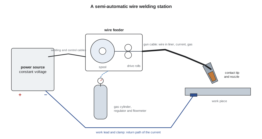
A wire welding setup is a chain: power source, feeder, gun cable, contact tip, arc, plate, work lead and back to the power source, with a gas line running alongside. A weak link anywhere in the chain shows up at the arc as spatter, porosity, a wandering arc or a wire that stops and starts. Marta Kowalchuk teaches Devon to troubleshoot from the wire spool to the work clamp before touching a setting, because most of the bad welds she has seen from good welders came from equipment, not technique. This lesson looks at each link: the constant-voltage power source and how its output is shaped, the wire feeder and its drive rolls, the gun, liner, contact tip and nozzle, and the cables that carry the current. It ends with a routine for setting up a station and a short list of feeding problems and their causes.
The constant-voltage power source
A welding power source converts high-voltage mains power to low-voltage, high-current direct current. Older wire welding machines are large transformer-rectifiers: a heavy transformer steps the voltage down and a bank of diodes or thyristors turns it into direct current. Most machines sold today are inverters. An inverter first rectifies the mains supply, then switches it on and off tens of thousands of times a second through a small, light, high-frequency transformer, and rectifies it again. Because the switching is controlled by electronics, an inverter can shape its output very precisely, change it from microsecond to microsecond, and offer several processes from one box: constant voltage for wire, constant current for stick and tungsten arc welding, and special programs for pulsing.
A constant-voltage power source is not perfectly constant. Its static volt-ampere curve, the line that shows output voltage against output current, slopes gently downward: perhaps one or two volts lower for every hundred amperes more. A stick power source has a steep curve that keeps the current nearly constant while the voltage changes with arc length. The difference is what makes the wire arc self-regulating: on the flat curve, a small change in arc length makes a large change in current, which corrects the arc length quickly.
Slope, inductance and arc control
Two adjustments shape how a constant-voltage machine responds when the wire touches the pool. Slope is the steepness of the static curve; a little more slope limits how high the current can go in a short circuit. Inductance slows the rate at which current rises when the wire shorts. In short-circuit transfer, the wire touches the pool many times a second, and each short makes the current climb. With too little inductance, the current rises so fast that the short explodes violently and throws spatter. With more inductance, the current rises more slowly, the droplet pinches off gently, and the arc sounds smoother and the pool wets out better; too much inductance and the wire stubs and the arc becomes sluggish. On older machines inductance was a tap on a choke; on inverters it is a knob or menu setting often called arc control or pinch. The welder's ear is the main tool here: a steady, crisp crackle like bacon frying is the sign of a well-tuned short-circuit arc.
Polarity
Almost all GMAW and gas-shielded FCAW is done with direct current electrode positive, DCEP, also called reverse polarity: the gun cable connects to the positive terminal and the work lead to the negative. DCEP gives a stable arc, good penetration and smooth metal transfer with solid wires. Many self-shielded flux-cored wires are designed for direct current electrode negative, DCEN, which puts more heat into the wire and less into the plate and makes the slag and gas formers in the core work as intended. A self-shielded wire run on the wrong polarity makes a harsh, spattery arc and porous welds. The polarity is part of the wire's classification and is printed on its label, and many feeders have a polarity reversing lead or a switch. Before changing wires, Devon learns to check the polarity first.
Duty cycle
A welding power source heats up while it delivers current. Its duty cycle rating tells how many minutes out of ten it can deliver a stated current without overheating, at a stated ambient temperature. A machine rated at 300 A at 60 percent duty cycle can deliver 300 A for six minutes in every ten. Wire welding runs long arcs at high current, so a machine that is fine for stick welding can be too small for heavy flux-cored work on a carriage. An approximate rule lets a welder estimate other combinations: the square of the current times the duty cycle stays about the same. Modern machines protect themselves with a thermal cutout, but a machine that keeps tripping is telling the welder it is undersized for the job.
# Duty cycle: allowable current at other duty cycles (approximate I^2 x duty rule)
rated_amps, rated_duty = 400, 60     # from the nameplate
for duty in (100, 80, 60, 40):
    amps = rated_amps * (rated_duty / duty) ** 0.5
    print(f"{duty:3} % duty cycle -> about {amps:4.0f} A")
job_amps = 320
duty_ok = rated_duty * (rated_amps / job_amps) ** 2
print(f"At {job_amps} A the machine allows about {min(duty_ok, 100):.0f} % duty cycle")100 % duty cycle -> about 310 A 80 % duty cycle -> about 346 A 60 % duty cycle -> about 400 A 40 % duty cycle -> about 490 A At 320 A the machine allows about 94 % duty cycle
The wire feeder
The feeder holds the spool on a hub with a brake, straightens and drives the wire with one or two pairs of drive rolls, and controls the wire feed speed. Inside, a motor turns the rolls through a gear train; a tachometer or encoder measures the actual speed so the feeder can hold it constant as the load changes. On the front panel, the welder sets wire feed speed and often reads the voltage from the power source, which may be remote-controlled through the feeder cable. Some portable feeders are voltage-sensing: they take their power from the arc voltage itself through the gun cable and need only the welding cable to run, which is handy in the field.
Drive rolls must match the wire:
- V-groove rolls for solid steel wire. The smooth V grips a hard wire without marking it.
- Knurled or serrated V-groove rolls for flux-cored and metal-cored wire. The teeth grip the softer tubular wire without needing so much pressure that it flattens.
- U-groove rolls for aluminum and other soft wires, which a V-groove would deform.
The roll groove must also match the wire diameter. Tension on the rolls should be just enough to feed without slipping: Marta's test is to feed the wire into a gloved hand or a block of wood at the contact tip and increase the tension until the rolls stop slipping, then add about half a turn. Too much tension flattens tubular wire, shaves metal off solid wire into the liner, and spills the core of flux-cored wire. The spool hub brake should stop the spool when the trigger is released without letting the wire overrun and loop off the spool, and without dragging so hard that the rolls slip.
| Wire | Drive roll | Liner | Typical note |
|---|---|---|---|
| Solid carbon steel | V-groove | Steel spiral | Moderate tension |
| Flux-cored or metal-cored | Knurled V-groove | Steel spiral, sized for the wire | Light tension so the tube is not crushed |
| Stainless solid | V-groove | Steel spiral or plastic | Keep separate from carbon steel |
| Aluminum | U-groove | Plastic (nylon or PTFE type) | Short cable, push-pull gun or spool gun |
Guns, cables and liners
The gun cable carries the welding current, the gas, the wire inside its liner, and the trigger wires. The liner is a coiled steel tube, or a plastic tube for aluminum, sized to the wire. It wears over time and collects dust and shavings, and a kinked or dirty liner is the most common cause of erratic feeding. Liners are trimmed to an exact length when they are replaced; one cut too short leaves a gap at the gun where the wire can bunch up. The cable should lie as straight as possible; every tight loop adds friction. A gun cable longer than about 4.5 m (15 ft) makes feeding harder, especially with soft wires.
Guns are air-cooled or water-cooled. An air-cooled gun relies on the gas flow and the mass of its parts to carry away heat and is rated at a current and duty cycle with a particular gas: a gun rated for a given current on carbon dioxide may be rated lower on argon mixes, which run hotter at the gun. Water-cooled guns circulate coolant through the cable and the gun neck and are used for long, high-current welding on carriages and robots. A gun run beyond its rating overheats the contact tip and liner and burns the operator's hand.
At the front of the gun are the consumables:
- The gas diffuser holds the contact tip and spreads the gas evenly into the nozzle.
- The contact tip is a copper alloy tube whose bore matches the wire diameter. The welding current transfers from the tip to the wire through a small contact area near the end. As the bore wears oval, the contact point wanders and the arc becomes unstable. Tips are cheap and are changed often.
- The nozzle directs the shielding gas. Its diameter, and how far the contact tip is recessed inside it or sticks out beyond it, are chosen for the transfer mode and joint: a flush or slightly protruding tip for short-circuit welding in tight joints, a recessed tip for spray transfer at high current.
- Nozzle dip or anti-spatter spray keeps spatter from sticking. Spatter that bridges the tip and nozzle can short them together and disturb the gas flow.
Cables and voltage drop
The voltage the welder sets on the power source is not quite the voltage at the arc. Every metre or foot of welding cable has resistance, and the welding current flowing through it loses a little voltage on the way out and back. On a short shop setup the loss is small, but in the field with long leads, or with an undersized work lead, it can be several volts. A procedure written for 26 V at the arc will then be run at 22 or 23 V without anyone noticing. Many feeders measure voltage at the feeder or at the gun through a sense lead for this reason, and Lucia Ferreira checks procedure voltages with a meter across the gun and the work, not on the power source display.
# Voltage drop in welding cables: what the arc actually gets
rho = 0.0172e-6            # resistivity of copper, ohm metre
cables = [  # description, length m, cross-section mm2
    ("gun cable (built in)", 4.5, 50),
    ("feeder extension", 15, 70),
    ("work lead", 20, 70),
]
amps = 280
set_volts = 27.0
total = 0.0
for name, length, area in cables:
    metres = length * 1
    r = rho * metres / (area * 1e-6)
    drop = amps * r
    total += drop
    print(f"{name:22} {length:4} m  drop {drop:4.2f} V")
print(f"Total drop {total:.2f} V; about {set_volts - total:.1f} V reaches the arc")gun cable (built in) 4.5 m drop 0.43 V feeder extension 15 m drop 1.03 V work lead 20 m drop 1.38 V Total drop 2.84 V; about 24.2 V reaches the arc
Two volts is enough to turn a spray arc into a globular one, or to make a short-circuit arc stubby and cold. The cure is to use large enough cables, keep them short, keep connections tight and clean, and measure at the arc.
The work connection
The work clamp completes the circuit, and a poor connection causes unstable arcs, heats the clamp and can even send welding current through bearings, hoist chains or building steel. Marta's rules from stick welding apply here too: clamp onto clean metal on the part being welded, as close to the joint as practical; never clamp to a part that the current would then flow through to reach the weld; and on long girders or large weldments, place the clamp so the current path does not cause arc blow. On the Riverside girders, the shop uses a large copper clamp on a cleaned spot of the flange near each weld rather than relying on the fixture table.
Setting up a station
Devon writes the setup routine in his notebook:
- Check the power source, feeder and gun ratings against the job, and set the polarity for the wire.
- Fit drive rolls, liner, contact tip and nozzle for the wire type and diameter.
- Load the spool so the wire comes off the correct side, cut off any bent end, and feed it through the rolls by hand before closing them.
- Set drive roll tension and spool brake.
- Remove the contact tip, feed wire through the gun with the cable straight, then refit the tip and trim the wire to the right stickout.
- Connect the gas, set the flow at the flowmeter with the trigger pulled, and check for leaks.
- Attach the work clamp to clean metal.
- Set wire feed speed and voltage from the procedure, run a test bead on scrap, and check the voltage and current at the arc.
Feeding problems and their causes
| Symptom | Likely causes |
|---|---|
| Wire stops and starts, arc surges | Kinked or dirty liner, worn contact tip, drive roll tension too low, cable coiled tightly |
| Wire bunches up behind the rolls (bird's nest) | Too much drag in the liner or tip, burnback, tension too high, wrong liner size |
| Wire burns back into the tip | Contact tip too close to the work, burnback delay too long, feed slipping, low wire speed for the voltage |
| Flattened or shaved wire | Drive roll tension too high, wrong roll groove or size |
| Wire loops off the spool | Spool brake too loose |
| Unstable arc with good feeding | Loose work clamp, loose cable lug, worn tip, voltage drop in long leads |
Common mistakes
MistakeUsing smooth V-groove rolls on flux-cored wire and cranking up tension until it feeds.
InsteadUse knurled rolls with light tension so the tube is not crushed.
MistakeRunning a self-shielded wire on DCEP because the machine was left that way.
InsteadSet the polarity the wire label calls for.
MistakeReading the procedure voltage off the power source display on a long field lead.
InsteadMeasure at the gun and work; cables lose voltage.
MistakeLeaving a worn, oval contact tip in the gun.
InsteadChange tips often; they are the cheapest fix for an unstable arc.
MistakeCoiling the gun cable in tight loops.
InsteadKeep the cable as straight as possible to reduce liner drag.
Summary and key terms
- Wire processes use constant-voltage power sources whose nearly flat output curves make the arc self-regulating.
- Inductance or arc control sets how fast current rises in a short and controls spatter in short-circuit transfer.
- GMAW and FCAW-G normally run DCEP; many FCAW-S wires run DCEN.
- Duty cycle limits how long a machine or gun can carry a given current.
- Drive rolls, liners and contact tips must match the wire type and diameter.
- Cable resistance reduces the voltage at the arc; long leads need larger cables and voltage checks at the gun.
- Most feeding problems come from liners, tips, tension or cable layout.
- Inverter
- A power source that switches rectified mains power at high frequency through a small transformer and shapes its output electronically.
- Static volt-ampere curve
- The relationship between output voltage and current of a power source.
- Inductance
- A setting that controls how quickly current rises when the wire shorts to the pool.
- DCEP
- Direct current electrode positive, also called reverse polarity.
- Duty cycle
- The percentage of a ten-minute period a machine can deliver a rated current.
- Liner
- The tube inside the gun cable that guides the wire.
- Contact tip
- The copper alloy tube that transfers welding current to the wire.
- Burnback
- The wire melting back to fuse with the contact tip.
Practice problems
Work each problem on paper first, then reveal the answer to check.
A machine is rated 350 A at 60 percent. About how much current can it deliver at 100 percent?
Show answer
350 × √0.6 ≈ 271 A.
Which drive roll groove is used for metal-cored wire?
Show answer
A knurled V-groove with light tension.
A 280 A arc runs through leads with a combined resistance of 0.006 ohm. What is the voltage drop?
Show answer
280 × 0.006 = 1.7 V.
Lesson quiz · 5 questions
Score 60% or more to complete this lesson.
Create a free account to save your progress, take quizzes and earn a certificate.