
WLD-130 · Lesson 12 of 12 · 21 min
Capstone: choosing preheat and controlling distortion on a repair
On a Monday in early spring, a farmer from near Leduc, Wes Brandvold, backs a tractor with a front-end loader into Hartwell's repair bay. The left boom arm has a crack about 90 mm (3-1/2 in) long running from the toe of an old weld at the bracket where the bucket tilt cylinder mounts. The loader is needed for calving season in two weeks, and Wes wants it welded today. Glen Teskey gives the job to Marta Kowalchuk, with Devon Okafor assisting and Lucia Ferreira handling the inspection. Marta tells Devon that this is the metallurgy course in one job. Before anyone strikes an arc, they will find out what the steel is, why it cracked, how much preheat it needs, how to keep the boom straight so the pins still line up, and how they will know the repair is sound. This capstone follows the job from the first look to the release, with Devon writing the repair plan.
Step 1: Look, measure and stop the damage
Marta and Devon start with the loader on the floor, bucket down and resting on blocks, the hydraulic system relieved and the tractor locked out according to the shop's procedure. They clean the area around the crack with a solvent and a wire brush and Lucia runs a magnetic particle test with a yoke and a red visible powder. The test shows the full length of the crack, about 95 mm (3-3/4 in), a little longer than it looked, starting at the toe of an old fillet weld around the bracket and running into the boom side plate. A second, much shorter indication sits at the other end of the same old weld. The old weld itself is lumpy, undercut at the toe and covered in old paint.
Devon measures the boom: side plates 20 mm (3/4 in) thick, the bracket 25 mm (1 in) thick, the pin bores for the cylinder and the bucket. With a straight bar through both bucket pin bores and a tape, he records the distance between the two boom arms at three points and the alignment of the bores. These numbers are the baseline for distortion control. If the repair pulls the left arm in by even a few millimetres, the bucket pins will bind.
Step 2: Identify the material
The boom is not a code structure with a mill test report. Devon looks up the manufacturer's service information through the dealer, who confirms that the boom side plates are a high-strength low-alloy steel with a minimum yield strength around the 350 MPa or 50 ksi class, and that weld repairs are permitted on the boom arms, but not on the pins, bushings or cylinder rods, using low-hydrogen electrodes and preheat. To be sure, Lucia takes a reading with the shop's handheld optical emission analyzer on a ground spot away from the crack.
| Element | C | Mn | Si | Cr | Mo | V | Ni | Cu |
|---|---|---|---|---|---|---|---|---|
| Percent | 0.19 | 1.42 | 0.30 | 0.12 | 0.04 | 0.05 | 0.15 | 0.22 |
The bracket, a thicker piece added at the factory, reads almost the same. The steel is weldable, but with more carbon and manganese than the shop's usual structural plate.
# Step 2: carbon equivalent and Pcm of the boom steel
chem = dict(C=0.19, Mn=1.42, Si=0.30, Cr=0.12, Mo=0.04, V=0.05, Ni=0.15, Cu=0.22, B=0.0)
ce = chem["C"] + chem["Mn"] / 6 + (chem["Cr"] + chem["Mo"] + chem["V"]) / 5 + (chem["Ni"] + chem["Cu"]) / 15
pcm = (chem["C"] + chem["Si"] / 30 + (chem["Mn"] + chem["Cu"] + chem["Cr"]) / 20 + chem["Ni"] / 60
       + chem["Mo"] / 15 + chem["V"] / 10 + 5 * chem["B"])
hv_mart = 884 * chem["C"] * (1 - 0.3 * chem["C"] ** 2) + 294
print(f"IIW CE = {ce:.2f}   Pcm = {pcm:.3f}")
print(f"Fully martensitic HAZ would be about {hv_mart:.0f} HV")
print("CE above 0.45: preheat, low hydrogen and controlled cooling are required")IIW CE = 0.49 Pcm = 0.298 Fully martensitic HAZ would be about 460 HV CE above 0.45: preheat, low hydrogen and controlled cooling are required
With a carbon equivalent near 0.49, the coarse-grained HAZ could form hard martensite near 460 HV if the joint cools fast. Hydrogen cracking is a real risk in 20 to 25 mm (3/4 to 1 in) plate under the restraint of a closed boom section.
Step 3: Work out why it cracked
Marta asks Devon to explain the crack before planning the repair, because a repair that copies the original weld will fail the same way. Devon writes it down in three ingredients and one mechanism:
- Microstructure: a CE near 0.49 steel, with a fillet on 25 mm (1 in) bracket, cools fast enough to harden the HAZ without preheat.
- Hydrogen: the old weld has the coarse ripple and heavy slag pattern of a general-purpose electrode, not a low-hydrogen one, and it was probably made in a cold shed.
- Stress: the bracket fillet sits on a highly restrained, heavily loaded part, and the undercut toe is a sharp notch.
- Mechanism: a small hydrogen crack or the undercut itself at the toe became the start of a fatigue crack, which has grown with every bucket load since.
Lucia agrees, with one addition: the crack running out of a fillet toe across a boom side plate is a typical fatigue crack, so the repair must remove the whole old weld and its HAZ at the toe, not just the visible crack, and must leave a smooth toe.
Step 4: Remove the crack
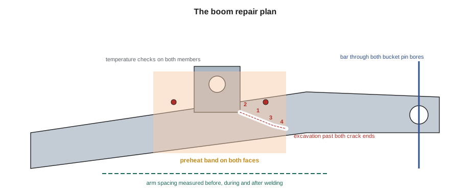
The plan is to remove the old bracket fillet and the crack completely and reweld them as a groove repair with a new fillet over it. Because air carbon arc gouging is itself a fast thermal cycle on a hardenable steel, the area is preheated before gouging, to the same temperature as for welding. Devon gouges a U-shaped groove along the crack, to sound metal and about 15 mm (about 5/8 in) past each end, then grinds the groove smooth and bright, removing the carburized gouging surface. Lucia repeats the magnetic particle test in the groove, now cooled to a safe handling temperature for the test, and confirms no indication remains. The groove reaches about two thirds of the plate thickness at the deepest point and is opened to a shape the electrode can reach, with a rounded bottom and side walls of about 20 degrees.
Step 5: Choose the preheat
Devon works through the preheat three ways and takes the most demanding answer. First, the structural code tables for a 350 or 50 ksi class steel with low hydrogen at 25 mm (1 in) would call for only a modest preheat, but the boom steel's CE is higher than the steels those tables cover and the joint is a highly restrained repair, so the tables are a lower bound only. Second, the illustrative susceptibility index method from the preheat lesson, with an H4 electrode and high restraint, gives a higher figure. Third, the manufacturer's service information calls for a minimum preheat range for boom repairs. Marta's experience agrees with the higher answer. The plan sets a minimum preheat and interpass of 120 °C (250 °F) and a maximum interpass of 230 °C (450 °F), with preheat measured 75 mm (3 in) from the joint on both the side plate and the bracket.
# Step 5: preheat from three sources; take the highest
import math
pcm = 0.298                 # from step 2
h = 4                       # H4 electrode, mL/100 g
index = 12 * pcm + math.log10(h)
groups = "ABCDEF"
limits = (3.0, 3.5, 4.0, 4.5, 5.0, 5.5)
group = next((g for g, lim in zip(groups, limits) if index < lim), "G")
# illustrative HIGH restraint row for 20-40 mm, by group, in C
high_restraint = {"A": 20, "B": 50, "C": 100, "D": 120, "E": 140, "F": 160, "G": 160}
sources = {
    "code table lower bound (350 class, low hydrogen)": 10,
    f"index method (index {index:.2f}, group {group}, high restraint)": high_restraint[group],
    "manufacturer service information (minimum)": 120,
}
for name, t in sources.items():
    print(f"{name:58} {t:4.0f} C")
chosen = max(sources.values())
print(f"Repair plan minimum preheat and interpass: {chosen:.0f} C")code table lower bound (350 class, low hydrogen) 10 C index method (index 4.18, group D, high restraint) 120 C manufacturer service information (minimum) 120 C Repair plan minimum preheat and interpass: 120 C
The heating is done with electric resistance pads borrowed from the pipe shop, wrapped on both sides of the boom arm over a band 150 mm (6 in) either side of the repair, with a thermocouple under one pad and contact probe checks on the opposite face. Devon also wraps the bracket, because the thick bracket would otherwise draw heat away from the root of the fillet.
Step 6: Set the welding parameters
The procedure uses SMAW with E7018-1 H4R electrodes, 3.2 mm (1/8 in) for the root and first layers in the narrow bottom of the groove and 4.0 mm (5/32 in) for fill and the fillet, taken from the holding oven in small batches and returned or discarded after the shop's exposure limit. Stringer beads only, no weaving wider than about two and a half times the electrode diameter. The heat input window is set to keep the HAZ from cooling too fast without overheating the boom.
# Step 6: heat input of the trial bead and the resulting thick-plate cooling time
import math
eff = 0.8
volts, amps = 23, 155
length, seconds = 150, 48          # bead length mm and time
speed = length / seconds * 60          # mm per minute
q = eff * 60 * volts * amps / (1000 * speed)       # kJ/mm
q_jmm = q * 1000                                     # J/mm
t0 = 120                                            # preheat, C
k = 0.025
t85 = q_jmm / (2 * math.pi * k) * (1 / (500 - t0) - 1 / (800 - t0))
t85_cold = q_jmm / (2 * math.pi * k) * (1 / (500 - 15) - 1 / (800 - 15))
print(f"travel {speed:.0f} mm/min, heat input {q:.2f} kJ/mm")
print(f"estimated t8/5 with preheat: {t85:.1f} s (without preheat it would be {t85_cold:.1f} s)")travel 188 mm/min, heat input 0.91 kJ/mm estimated t8/5 with preheat: 6.7 s (without preheat it would be 4.6 s)
The preheat lengthens the cooling time by about half compared with welding the boom cold, at the same heat input. The thick-plate estimate is rough, and in the narrow groove the real cooling is a little faster, but the comparison makes the point Marta wanted Devon to see: preheat, not a bigger bead, is the right way to slow the cooling.
Step 7: Plan the sequence and the distortion control
The repair is on one arm of a two-arm frame, on one side of the arm. Everything about it tends to pull the left arm toward the weld side and bow it. Devon's plan uses the methods from the distortion lesson:
- Fixture: a heavy bar bolted through both bucket pin bores, and a turnbuckle brace between the two arms near the repair, both set at the baseline measurements before heating. Nothing is tack welded to the boom.
- Smallest weld: the groove is excavated only as deep and wide as the crack requires, and the new fillet on the bracket is the size of the original design, not larger.
- Sequence: the groove is filled in short backstep segments of about 50 mm (2 in), starting in the middle of the repair and working out toward each end, alternating ends. Each layer is completed before the next is started, and the fillet around the bracket is made in balanced segments on opposite sides of the bracket.
- Heat control: the interpass maximum is checked before every pass, with a pause if needed, so the arm does not build up heat on one side.
- Measuring as it goes: Devon checks the distance between the arms and the pin alignment after the root layer, after half the fill and after the fillet.
# Step 7: estimated transverse shrinkage across the groove repair and the movement it could cause
groove_area = 160      # cross-section of the repair groove, mm2
plate = 20             # side plate thickness, mm
gap = 0                 # no root opening in a repair groove
shrink = 0.2 * groove_area / plate + 0.05 * gap
print(f"estimated shrinkage across the repair: {shrink:.1f} mm")
# shrinkage on one face of the arm near the bracket tends to bend the arm; scale it to the pin position
lever = 900           # distance from the repair to the bucket pin, mm
arm_depth = 220       # depth of the arm section, mm
rotation = shrink / arm_depth                     # radians, rough
print(f"rough pin movement if unrestrained: {rotation * lever:.1f} mm")
print("fixture and balanced backstep sequence are planned to keep it within the bushing clearance")estimated shrinkage across the repair: 1.6 mm rough pin movement if unrestrained: 6.5 mm fixture and balanced backstep sequence are planned to keep it within the bushing clearance
The rough estimate says that, unrestrained, the shrinkage of the groove alone could swing the pin by more than the bushing clearance. The fixture holds most of it, at the price of residual stress, which is one more reason the preheat, low hydrogen and slow cooling matter.
Step 8: Weld, measure and cool
The welding takes most of the afternoon. Marta welds the root and first layers, where access is tight; Devon, now cleared for fill passes on repair work under supervision, runs fill passes and part of the fillet while Marta watches. Before every pass, one of them checks the temperature with a crayon on each side and the contact probe, and Devon records it on the repair plan. Twice, the left side approaches the maximum interpass and they wait. Each pass is cleaned with a needle scaler and wire brush; each layer is inspected for slag and fusion before the next. The final passes are placed so the last beads land on earlier weld metal, not on the base metal, so their heat tempers the HAZ at the toes.
After the last pass, the pads are kept on and the temperature raised to about 250 °C (about 480 °F) for an hour as a hydrogen post-heat, as the plan specifies. Then the pads are switched off and the boom is wrapped in ceramic fibre blankets to cool slowly overnight. The arm measurements taken at the end of welding are within 1 mm (0.04 in) of the baseline.
Step 9: Finish the toe and inspect
The next morning, with the boom cold, Devon grinds the toes of the new fillet with a burr to a smooth, rounded profile, removing any undercut and blending the weld into the plate. Toe grinding improves fatigue life considerably on a part loaded like a loader boom, and it removes the sharp notch that started the original crack. Lucia waits until the repair has been cold for a full day, then examines it visually and repeats the magnetic particle test over the repair, the toes and 50 mm (2 in) of plate around them. There are no indications. Devon removes the fixture and remeasures the arms and the pin alignment: the bar slides through both bores, and the distance between the arms is unchanged.
# Step 9: release checklist for the boom repair
checks = {
    "material identified and CE calculated": True,
    "crack removed past both ends, MT clear before welding": True,
    "preheat 120 C minimum on both members, recorded every pass": True,
    "maximum interpass 230 C never exceeded": True,
    "low-hydrogen electrodes within exposure time": True,
    "post-heat and slow cooling completed": True,
    "toes ground smooth": True,
    "MT clear after at least 24 h": True,
    "pin alignment and arm spacing within tolerance": True,
}
for item, ok in checks.items():
    print(("[x] " if ok else "[ ] ") + item)
print("Release:", "yes" if all(checks.values()) else "no")[x] material identified and CE calculated [x] crack removed past both ends, MT clear before welding [x] preheat 120 C minimum on both members, recorded every pass [x] maximum interpass 230 C never exceeded [x] low-hydrogen electrodes within exposure time [x] post-heat and slow cooling completed [x] toes ground smooth [x] MT clear after at least 24 h [x] pin alignment and arm spacing within tolerance Release: yes
Step 10: Record and explain
Devon's repair plan, now completed with measurements and temperatures, goes into the job file with Lucia's inspection record and photographs. Glen writes the invoice and adds a note for Wes: the repair has removed the cause of the crack, but loader booms see heavy cycling, so the repaired area and the matching spot on the right arm should be checked at each service. Marta goes through the plan with Devon one more time and asks him what would have happened if the job had been done the way Wes first asked, welded the same day over the crack with whatever electrode was handy. Devon's answer covers the course: the crack would have been buried, not removed; the cold boom would have cooled the new weld fast enough to make a hard HAZ; the hydrogen from a general-purpose electrode would have found it; the restraint and the load would have supplied the stress; and the boom would likely have cracked again, perhaps with the bucket full.
Lucia's last comment is about the things that did not show: "The best part of this repair is everything you can't see in the bead. The steel was identified, the heat was controlled, the hydrogen was kept out and the shape was held. That's metallurgy on a shop floor."
Common mistakes
MistakeWelding over a crack to save time.
InsteadRemove the crack completely, past its ends, and confirm with testing.
MistakeChoosing preheat from the code table alone on an unknown, restrained repair.
InsteadCheck the chemistry, the restraint and the manufacturer's requirements; take the most demanding answer.
MistakeTack welding a fixture to a loader boom.
InsteadBolt or clamp fixtures; stray welds on a fatigue-loaded part start cracks.
MistakeInspecting the repair as soon as it is cool to touch.
InsteadWait the required time for any delayed hydrogen cracking.
MistakeLeaving an undercut or sharp toe on a cyclically loaded part.
InsteadGrind the toes smooth to improve fatigue life.
Summary and key terms
- A repair starts with locking out, cleaning, testing and baseline measurements.
- Identify the material and calculate its carbon equivalent before choosing a procedure.
- Find the cause of the original crack so the repair does not repeat it.
- Preheat before gouging and welding; take the most demanding of code, calculation and manufacturer requirements.
- Use dry low-hydrogen electrodes, stringer beads and controlled heat input and interpass temperature.
- Control distortion with fixtures, the smallest weld and a balanced backstep sequence, measuring as you go.
- Post-heat, cool slowly, grind the toes, inspect after a delay, and record everything.
- Repair plan
- A written plan for a weld repair covering material, removal, preheat, procedure, sequence and inspection.
- Magnetic particle testing
- A test that reveals surface and near-surface cracks in magnetic steel with magnetic powder.
- Baseline measurement
- Dimensions recorded before welding to check distortion afterwards.
- Toe grinding
- Grinding the weld toe to a smooth profile to improve fatigue life.
- Inspection delay
- A waiting period before final inspection to allow delayed cracks to appear.
- Temper pass
- A final pass placed so its heat tempers the HAZ of earlier passes.
Practice problems
Work each problem on paper first, then reveal the answer to check.
Why was the boom preheated before gouging as well as before welding?
Show answer
Gouging is a fast thermal cycle that can harden and crack the steel; preheat slows its cooling.
The code table gives 10 °C, the calculation 120 °C and the manufacturer 120 °C. What preheat is used?
Show answer
The highest, 120 °C.
Why was nothing tack welded to the boom for the fixture?
Show answer
Stray welds on a fatigue-loaded, hardenable part create hard spots and start cracks.
Lesson quiz · 5 questions
Score 60% or more to complete this lesson.
Create a free account to save your progress, take quizzes and earn a certificate.