
WLD-120 · Lesson 3 of 12 · 16 min
Cables, holders, work connections and machine setup
A good weld depends on a good circuit. Between the machine's output studs and the arc there are connectors, lugs, two cables, a holder and a clamp, and every one of them carries the full welding current. A cable that is too small or too long robs the arc of voltage; a loose lug or a worn holder gets hot; a work clamp on painted steel makes the arc unstable; a damaged cable is a shock and fire hazard. The first course explained the electrical safety side of the welding circuit and why the work clamp belongs close to the weld. This lesson is about the hardware itself: choosing and inspecting cables, connectors, electrode holders and work clamps, working out voltage drop on a long run, and setting up a booth or a field job before the first arc. Marta's rule for Devon is that ten minutes spent setting up properly saves an hour of chasing a bad arc.
Welding cable
Welding cable is made of many fine strands of copper, sometimes aluminium on very long runs, covered with a tough, flexible jacket of rubber or a synthetic elastomer that resists oil, abrasion, heat and cold. The fine stranding is what lets it flex thousands of times without breaking; ordinary building wire with a few thick strands would crack in a week. Cable is sized by its copper cross-section, given in Canada in square millimetres and also, in both countries, by American Wire Gauge, AWG, where sizes larger than 1 are written 1/0, 2/0, 3/0 and 4/0 and spoken as one-ought, two-ought and so on. A bigger cross-section carries more current with less heating and less voltage drop.
The cable size for a job depends on two things: the current and the total length of the welding circuit, which is the electrode lead plus the work lead. A cable that is adequate for 150 A over a short booth run may be far too small for the same current at the end of 50 m (150 ft) of lead from a service truck. Manufacturers publish tables that pair current and circuit length with a minimum cable size, generally chosen so that the cable does not overheat at the duty cycle used and the voltage lost in the cable stays within a few volts.
| Cable size | Copper area (mm²) | Typical use |
|---|---|---|
| #2 AWG | 33.6 | Booth leads up to about 200 A on short runs |
| #1 AWG | 42.4 | General shop leads |
| 1/0 AWG | 53.5 | Heavier shop and short field runs |
| 2/0 AWG | 67.4 | Field leads, longer runs, higher current |
| 3/0 AWG | 85.0 | Long field runs and gouging |
| 4/0 AWG | 107.2 | Very long runs and high-current gouging |
Voltage drop
Copper has resistance, and current through a resistance loses voltage. Every volt dropped in the leads is a volt the arc does not get. A long, thin lead makes the arc feel weak and sluggish, harder to strike and more likely to stick, and the welder's natural response is to turn up the current, which heats the cable further. The drop can be estimated from the resistivity of copper, the length of the whole circuit and the cable area. Long coiled leads also add inductance, which affects the arc on AC and during the rapid changes of an arc start, so leads are laid out rather than left coiled.
Here I is current in amperes, rho is the resistivity of copper, about 0.0172 ohm·mm² per metre at room temperature, L is the total circuit length in metres, and A is the copper area in square millimetres. Warm cable has a higher resistance.
# Voltage drop in the welding leads
rho = 0.0172                 # resistivity of copper (ohm mm2 per m) at about 20 C
amps = 150                   # welding current (A)
electrode_lead = 35        # electrode lead length (m)
work_lead = 25             # work lead length (m)
circuit_m = (electrode_lead + work_lead) * 1.0
sizes = {"#2 AWG": 33.6, "#1 AWG": 42.4, "1/0 AWG": 53.5, "2/0 AWG": 67.4, "3/0 AWG": 85.0}
print(f"circuit length {electrode_lead + work_lead} m, current {amps} A")
for name, area in sizes.items():
    ohms = rho * circuit_m / area
    drop = amps * ohms
    heat_w = amps ** 2 * ohms
    flag = "  too much drop" if drop > 4 else ""
print(f"{name:8s} {area:6.1f} mm2 drop {drop:4.1f} V heat in cable {heat_w:5.0f} W{flag}")circuit length 60 m, current 150 A #2 AWG 33.6 mm2 drop 4.6 V heat in cable 691 W too much drop #1 AWG 42.4 mm2 drop 3.7 V heat in cable 548 W 1/0 AWG 53.5 mm2 drop 2.9 V heat in cable 434 W 2/0 AWG 67.4 mm2 drop 2.3 V heat in cable 345 W 3/0 AWG 85.0 mm2 drop 1.8 V heat in cable 273 W
The 4 V limit in the program is a rule of thumb used by several manufacturers, not a code limit. At this length, #2 cable would waste about 4 V of a 24 V arc and dissipate several hundred watts along its length, and 2/0 halves that. Hartwell's service trucks carry 2/0 leads for exactly this reason.
Connections and lugs
Each end of each cable needs a connection that carries current without heating. At the machine, cables end in copper lugs bolted to the output studs, or in twist-lock connectors that plug into sockets on the front panel. Lugs are crimped or soldered to the conductor; a loose or corroded lug shows as discoloured copper, a burnt smell, a hot spot on the jacket or an arc that fades in and out. Twist-lock connectors must be fully inserted and turned until they lock; a half-turned connector heats and can weld itself in the socket.
Cables are joined to extend them with insulated cable connectors made for welding cable, matched in size, so that no bare metal is exposed. Taping two lugs bolted together is not acceptable, because the tape is cut by the first sharp edge it crosses. Splices in the jacket are repaired only with materials and methods meant for welding cable, and a cable with repeated damage or exposed strands within a few metres of the holder is replaced. Devon's first job at the start of each shift is to walk the leads from the machine to the booth, checking for cuts, bare copper and hot spots from the day before.
Electrode holders
The electrode holder, called the stinger, clamps the bare end of the electrode and connects it to the electrode lead. Most holders have spring-loaded jaws with grooves that hold the electrode at several angles, and a fully insulated body and jaw shell. Holders are rated by current, for example 200, 300 or 500 A. A holder rated too low for the current heats up, which is uncomfortable and also damages the jaw contacts and the cable connection inside the handle.
Inspection before use: jaw insulation intact with no exposed metal except the gripping surfaces, the cable connection inside the handle tight, the jaws clean and not pitted by arcing, and the spring strong enough to grip the electrode firmly. A worn holder lets the electrode slip or arc against the jaws, which pits them further. When the holder is set down, it is hung on an insulated hook or laid where it cannot touch the work or grounded metal, and the stub is removed. Holders are never cooled by dipping them in water.
Work clamps and the work connection
The work clamp connects the work lead to the work. Spring clamps suit light booth work; screw clamps and C-clamps give a firmer contact on heavy work; magnetic clamps are quick on flat steel but must have a clean, flat contact face; rotary clamps let pipe turn while the connection stays tight. Whatever the type, the clamp is rated for the current and its jaws contact clean, bare metal. Paint, mill scale, rust and galvanizing all add resistance. A quick pass with a grinder or wire brush where the clamp goes is part of setup.
As the first course explained, the clamp goes on the work piece or on the fixture holding it, close to the weld, so welding current stays in the welding circuit and does not wander through building steel, conduit, bearings or rigging. In the booth the work sits on a steel table and the clamp is on the table, which is part of the work; on a fabrication, the clamp is moved along with the welder. Clamping position also affects arc blow, as the previous lesson showed.
Setting up the machine
Before the first arc, the welder sets up the machine for the electrode and the job:
- Check the machine is on a suitable supply, its frame is grounded through the supply cord, and its inspection tag is current.
- Select the process, usually marked SMAW or stick, on a multiprocess machine.
- Set current type and polarity to suit the electrode: for E7018 on a DC machine, electrode positive.
- Set the current within the electrode manufacturer's range for the size and position, starting near the middle and adjusting by test.
- Set arc force and hot start if the machine has them; for low-hydrogen electrodes a moderate setting is a common starting point.
- Turn on the voltage-reducing device if the job is in a wet or enclosed location.
- Strike a test bead on scrap of the same thickness and adjust.
Machine dials are not always accurate, and the current at the arc depends on cable length and condition. Hartwell's welding procedures give a current range, and inspectors check actual current with a clamp-on meter at the lead. Devon learns to read the meter on a test plate and compare it with the dial, and finds the dial on booth 3 reads about 10 A high.
# Compare dial setting with measured current and check against the procedure range
dial = 130            # current set on the machine (A)
measured = [118, 121, 119, 122, 120]   # clamp-meter readings during a test bead (A)
low, high = 110, 140                  # procedure range for 3.2 mm E7018 flat (A)
avg = sum(measured) / len(measured)
print(f"average measured {avg:.0f} A, dial {dial} A, offset {dial - avg:+.0f} A")
if low <= avg <= high:
    print(f"inside the procedure range {low}-{high} A")
else:
    print(f"outside the procedure range {low}-{high} A: adjust the dial")
target = (low + high) / 2
print(f"to get about {target:.0f} A at the arc, set the dial near {target + (dial - avg):.0f} A")average measured 120 A, dial 130 A, offset +10 A inside the procedure range 110-140 A to get about 125 A at the arc, set the dial near 135 A
Setting up a booth and a field job
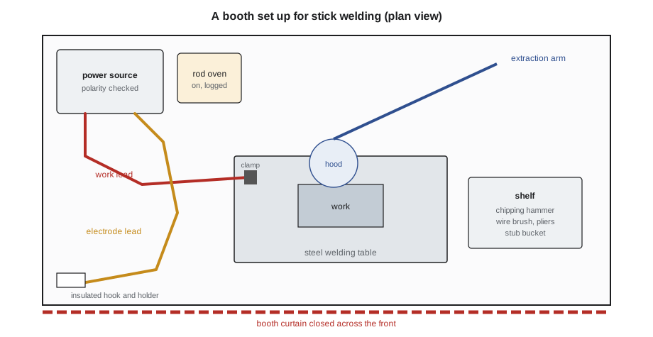
In the booth, the setup also includes the screens or curtains closed so other workers are protected from the arc, the fume extraction arm positioned close to the work, the rod oven switched on and holding temperature, a bucket for stubs, and the chipping hammer, wire brush, pliers and grinder within reach. Combustibles are kept out of the booth, and a fire extinguisher is at the booth entrance.
On a field job the same items are checked under harder conditions. On the second day of the Riverside bridge, Glen sends Marta and Devon to the erection site to tack temporary lifting lugs on a floor beam. The engine drive sits on the access road. Devon runs the 2/0 leads off the walkway and away from the crane's path, checks for damage along the full length, connects the work clamp to the floor beam itself after grinding a clean patch, and sets up a portable rod oven powered from the welder's auxiliary outlet. The leads total about 70 m (230 ft), so Marta has Devon run the program above with the real length before choosing the current.
Lead management on a busy site
On a site with several trades, welding leads are part of everyone's environment. They are run along the edges of walkways, never across ladders or stairs, and lifted overhead on hooks or bridged with cable protectors where vehicles cross. They are kept clear of pinch points such as doors, hatches and crane rails. At the end of the shift the leads are coiled in long loops and stored off the ground, and any damage found while coiling is tagged for repair, so the next shift starts with sound leads.
Common mistakes
MistakeLeaving extra lead coiled tightly beside the machine.
InsteadLay excess lead out in long loops; tight coils add inductance and heat.
MistakeJoining two leads by bolting the lugs and wrapping them in tape.
InsteadUse insulated cable connectors sized for the cable.
MistakeTurning the current up because a long lead feels weak.
InsteadCheck the voltage drop and use a larger cable or shorter run.
MistakeClamping the work lead to painted or rusty steel.
InsteadGrind a clean spot and clamp to bare metal on the work.
MistakeUsing a holder with cracked jaw insulation.
InsteadReplace it; exposed metal is a shock and arcing hazard.
Summary and key terms
- Welding cable is finely stranded and sized by area or AWG; size depends on current and total circuit length.
- Voltage drop is I times the cable resistance; keep it within a few volts by sizing leads for the run.
- Lugs, connectors and splices must be tight, insulated and made for welding cable.
- Electrode holders are rated by current and inspected for insulation, jaw condition and grip.
- The work clamp goes on clean metal on the work, close to the weld.
- Machine setup covers process, polarity, current, arc force and a test bead, with the current checked at the lead.
- Stinger
- Shop term for the electrode holder.
- AWG
- American Wire Gauge, the system of cable sizes such as 1/0 and 2/0.
- Voltage drop
- Voltage lost along the leads because of their resistance.
- Twist-lock connector
- A cable plug that locks into a machine socket by turning.
- Work clamp
- The clamp that connects the work lead to the work.
- Clamp-on meter
- An ammeter that measures current by clamping around the cable.
Practice problems
Work each problem on paper first, then reveal the answer to check.
Estimate the voltage drop for 160 A through 80 m of circuit in 1/0 cable (53.5 mm²).
Show answer
0.0172 × 80 / 53.5 = 0.0257 ohm; 160 × 0.0257 = 4.1 V.
Why is welding cable finely stranded?
Show answer
So it can flex repeatedly without the conductor breaking.
What three things are checked on an electrode holder?
Show answer
Insulation intact, tight cable connection, jaws clean with a firm grip.
Lesson quiz · 5 questions
Score 60% or more to complete this lesson.
Create a free account to save your progress, take quizzes and earn a certificate.