
TRD-103 · Lesson 9 of 12 · 21 min
HVAC and mechanical drawings
Heating, ventilation and air conditioning, usually shortened to HVAC, keeps a building comfortable and its air healthy. The HVAC drawings show the equipment that heats, cools and moves air and water, and the ducts and pipes that carry them to every room. They are usually the busiest sheets in the set and, because ducts are big, they drive much of the coordination in the ceiling space.
Maya works for a mechanical contractor, so her company installs both the plumbing and the HVAC on Kingsway Tower. Even though she is a plumbing apprentice, she works alongside the sheet metal workers who install the ductwork and the pipefitters who install the heating and cooling piping, and she needs to read their drawings to keep her pipes out of their way. The HVAC sheets are numbered M-001 to M-701.
How the HVAC system on Kingsway Tower works
Understanding the system first makes the drawings much easier to read. Kingsway Tower's design is typical of mid-rise residential buildings:
- Each apartment has a small heat pump or fan coil unit in a closet or above the bathroom ceiling, which heats and cools the suite, with short supply ducts to the rooms and a return grille in the hallway.
- Each apartment also has an energy recovery ventilator, or ERV, that brings in fresh outdoor air and exhausts stale air from the kitchen and bathrooms, transferring heat and moisture between the two airstreams.
- A rooftop make-up air unit supplies tempered fresh air to the corridors, keeping them slightly pressurized so odours and smoke do not spread from the units.
- Hydronic piping, water pipes in a closed loop, connects the suite units to boilers and a cooling tower or chiller in the mechanical penthouse.
- The parking levels have large exhaust fans controlled by carbon monoxide and nitrogen dioxide sensors, which ventilate the garage when vehicle fumes build up.
Duct drawings
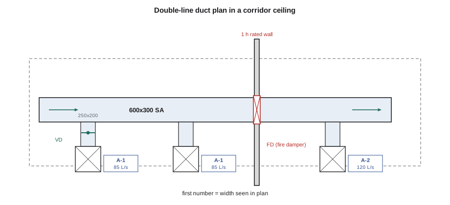
Ductwork can be drawn two ways. On single-line drawings, each duct is one line with its size written along it, which works at small scales. On double-line drawings, each duct is drawn as two lines showing its actual width, which shows clearly how much space it takes and is standard on larger-scale plans and coordination drawings.
Rectangular duct sizes are written as width by depth in millimetres, such as 600x300, where the first number is the side you see in plan and the second is the depth. Round ducts are written with a diameter symbol, such as Ø250. Some drawings use the opposite order, so the legend or general notes should say which; on Kingsway Tower the first number is always the width shown in plan.
Different air systems are distinguished by labels or line types: supply air (SA), return air (RA), exhaust air (EA), outdoor air (OA) and transfer air. Flexible duct, the short accordion-like round duct used for the last connection to a diffuser, is drawn with a wavy line. Arrows show the direction of airflow, and a duct turning up or down is drawn with a box containing a diagonal line or an X, depending on the convention in the legend.
Air devices and dampers
Diffusers, grilles and registers are the visible ends of the duct system. Each one carries a tag, such as a letter and number in a box, with the design airflow in litres per second, for example A-2 85 L/s. The tag links to the air device schedule, which gives the type, size, finish and pattern of each device. The positions of ceiling diffusers are coordinated with the reflected ceiling plan so that they line up with light fixtures and ceiling grid.
Dampers control or block airflow, and some of them are life-safety devices:
- Volume dampers are adjustable blades used to balance the airflow between branches.
- Fire dampers close automatically when heat melts a fusible link, stopping fire from passing through a fire-rated wall or floor along the duct.
- Smoke dampers and combination fire-smoke dampers are closed by the fire alarm system to stop smoke from spreading.
- Motorized dampers are opened and closed by the controls system.
Fire and smoke dampers need clear access panels so they can be inspected and reset, and the other trades must not block them. When Maya routes a pipe above a corridor ceiling, she checks the duct plan for damper symbols at every rated wall and keeps clear of the access side.
Hydronic and refrigerant piping
HVAC piping plans look much like plumbing plans, with their own legend. Common systems include heating hot water supply and return (HWS and HWR, or HHWS and HHWR), chilled water supply and return (CHWS and CHWR), condenser water, condensate drains from cooling coils, and refrigerant piping for split systems. Supply and return lines usually run in pairs, so a plan often shows two parallel lines with arrows in opposite directions.
Piping plans show valves, strainers, balancing valves, air vents and expansion fittings at the right locations, and the details show how the coils and terminal units connect. A flow diagram or schematic, usually not to scale, shows the whole hydronic system on one sheet: boilers, pumps, heat exchangers, expansion tanks and the main distribution, with every valve and sensor. Like a plumbing riser diagram, the schematic is the best place to understand how the system works before you look at where its pipes run.
Condensate drains are where HVAC and plumbing overlap. Cooling coils produce water that has to be carried away by gravity, so condensate lines need slope, traps and a legal point of discharge, often an indirect connection to a floor drain or hub drain through an air gap. Maya often installs the receptors that the condensate lines discharge into.
Equipment schedules and controls
Every piece of HVAC equipment is tagged, for example HP-405 for the heat pump in unit 405, ERV-405 for its ventilator, MAU-1 for the rooftop make-up air unit or EF-P1 for a parking exhaust fan. Equipment schedules list each tag with its capacity, airflow or water flow, motor size and electrical data: voltage, phase, full-load amps and the overcurrent protection required. The electrician reads the same schedule to size the circuits, so a mistake in one place affects two trades.
Controls drawings show how the system is controlled: thermostats and sensors on the plans, control diagrams for each system and a written sequence of operations explaining what the controls do, such as how the garage fans respond to gas levels or how the make-up air unit resets its discharge temperature. Sequences of operation are written in plain language and are some of the most readable parts of the mechanical drawings.
The ceiling space and coordination
Ducts are the largest services in the ceiling, so they set the limits for everything else. HVAC sections and coordination drawings give the bottom of duct elevation, often written as BOD with a level, or the height above finished floor. With the slab thickness, the ceiling height and the duct depth known, the remaining space for pipes, sprinklers and cable trays can be worked out, as lesson 6 showed.
On a project the size of Kingsway Tower, the trades build a combined three-dimensional model before installation. Each trade models its own work, and software runs clash detection to find places where a pipe passes through a duct, a duct hits a beam, or a cable tray blocks a damper access panel. The clashes are resolved in coordination meetings, and the agreed layout becomes the coordination drawings each trade installs from. A common rule of thumb in those meetings is that gravity drains get priority because they cannot go up and down freely, ducts come next because they are big, and smaller pressure piping and conduit fit around them.
Worked problem
Will the duct fit under the drain?
In the corridor on Level 4, the underside of the slab is at 2.700 above the finished floor. The sanitary drain from the floor above hangs with its bottom 150 mm below the slab. The corridor ceiling is at 2.400 AFF with 50 mm of framing above it. Can a duct 600x200 pass under the drain?
Show solution
- Bottom of drain: 2.700 - 0.150 = 2.550 AFF.
- Top of ceiling framing: 2.400 + 0.050 = 2.450 AFF.
- Space between them: 2.550 - 2.450 = 0.100 m, or 100 mm.
- The duct is 200 mm deep, which is 100 mm more than the space.
Answer: No. The duct must route around the drain, be flattened to a wider, shallower size approved by the engineer, or the drain must be moved. This is exactly the kind of clash coordination meetings exist to catch.
Duct sizes and airflow in code
Duct sizes come from the airflow each duct carries and the air speed the designer allows. This program finds the air velocity in a few ducts from the drawings and the size of a flatter duct with the same area, the first step when a duct has to be reshaped to fit a tight ceiling. A real reshaping must be approved by the engineer, who also accounts for friction and noise.
import math

ducts = [('SA-1', 600, 300, 0.9), ('SA-2', 400, 250, 0.45), ('EA-3', 250, 0, 0.12)]    # tag, width, depth (or diameter if depth is 0), airflow
for tag, w, d, q in ducts:
    area = (w * d if d else math.pi * w ** 2 / 4) / 1000000.0     # area in m²
    v = q / area / 1
    print(f"{tag:6s} {w}x{d if d else 'dia'}  area {area:.3f} m²  velocity {v:.1f} m/s")

# same area, flatter duct for a tight ceiling
w, d = (600, 200)
area = w * d
for new_d in [150, 100]:
print(f"depth {new_d}: width about {math.ceil(area / new_d / 50) * 50}")SA-1 600x300 area 0.180 m² velocity 5.0 m/s SA-2 400x250 area 0.100 m² velocity 4.5 m/s EA-3 250xdia area 0.049 m² velocity 2.4 m/s depth 150: width about 800 depth 100: width about 1200
A duct that is made much flatter has more surface area for the same cross-section, so it causes more friction and may need to be larger still. That is why the engineer, not the installer, decides on any change in duct size.
Mechanical rooms and roofs
The mechanical penthouse on the roof of Kingsway Tower is drawn on enlarged plans and sections, because it is packed with equipment: boilers, pumps, heat exchangers, expansion tanks, the domestic water heaters and the make-up air unit outside on the roof. These drawings show each piece of equipment by tag, the clearances needed in front of it for service, the housekeeping pads it sits on, and the main pipe and duct connections. Service clearances are easy to forget and hard to fix later. A pump that cannot be removed because a pipe was run across its access space, or an electrical panel whose required working space is blocked by a duct, will fail inspection or cost a great deal to correct. The enlarged plans show those spaces, and every trade working in the room should respect them.
Common mistakes
MistakeReading a duct size the wrong way round.
InsteadCheck the legend or notes; on most drawings the first number is the width seen in plan.
MistakeBlocking a fire damper access panel with pipe or conduit.
InsteadFind damper symbols at every rated wall and keep the access side clear.
MistakeAssuming the hydronic schematic is to scale.
InsteadSchematics show how the system works; plans show where the pipes run.
MistakeIgnoring the electrical data in equipment schedules.
InsteadEquipment schedules feed the electrical design; report any change in equipment to both trades.
MistakeReshaping a duct on site to fit.
InsteadDuct size changes need the engineer's approval because they change friction, noise and airflow.
Summary and key terms
- HVAC drawings show equipment, ductwork, hydronic and refrigerant piping, controls and schedules.
- Ducts are drawn single-line or double-line, with width by depth sizes and system labels such as SA, RA and EA.
- Air devices carry tags with airflow linking to the air device schedule.
- Fire, smoke and combination dampers are life-safety devices that need clear access.
- Equipment schedules give capacities and electrical data used by the electrician.
- Ducts drive coordination in the ceiling space; clash detection and coordination drawings resolve conflicts.
- HVAC
- Heating, ventilation and air conditioning.
- Double-line drawing
- A duct drawing showing both sides of each duct to its actual width.
- Diffuser
- A device that spreads supply air into a room.
- Fire damper
- A damper that closes automatically when heat melts its link, blocking fire through a rated assembly.
- Energy recovery ventilator (ERV)
- A unit that exchanges stale indoor air for fresh outdoor air while recovering heat and moisture.
- Hydronic
- Using circulating water to carry heat or cooling.
- Sequence of operations
- A written description of how a system is controlled.
- Clash detection
- Software checking of a combined model for places where building elements collide.
- Bottom of duct (BOD)
- The elevation of the underside of a duct.
Practice problems
Work each problem on paper first, then reveal the answer to check.
What does a duct label of 500x250 SA mean?
Show answer
A supply air duct 500 mm wide (in plan) and 250 mm deep.
What closes a fire damper?
Show answer
Heat melting a fusible link.
A diffuser tag reads B-1 120 L/s. What is 120 L/s?
Show answer
The design airflow for that diffuser.
Where do you find the voltage and amps for a heat pump?
Show answer
In the mechanical equipment schedule (and the electrical drawings).
What is the difference between a hydronic schematic and a piping plan?
Show answer
The schematic shows how the system connects, usually not to scale; the plan shows where pipes run.
Why do gravity drains usually get priority in ceiling coordination?
Show answer
They need constant slope and cannot rise and fall to avoid other services.
Lesson quiz · 5 questions
Score 60% or more to complete this lesson.
Create a free account to save your progress, take quizzes and earn a certificate.