
TRD-103 · Lesson 5 of 12 · 21 min
Site plans, grid lines and floor plans
Plans are the drawings you will use most. A plan is a view looking straight down, and on a building project there are plans at every scale: the site plan shows the whole property, floor plans show each storey, and enlarged plans zoom in on the crowded rooms. This lesson walks through the site plan and the floor plans of Kingsway Tower, and introduces the grid system that ties every sheet in the set together.
The site plan
The site plan shows the property and everything on it: the building footprint, roads, parking, sidewalks, landscaping and the underground services that connect the building to the city. It is drawn by the architect or civil engineer, or both, at a small scale. Even if your trade works entirely inside the building, the site plan tells you where water, sewer, gas and power come in, where materials are delivered, and where the site trailer, crane and storage areas are.
- Property lines mark the legal boundary of the site. They are drawn with a heavy long-dash, two-short-dash line and labelled with lengths and bearings, compass directions measured by surveyors.
- Setbacks are the minimum distances from the property lines that the building must keep, set by the zoning rules.
- The building footprint shows the outline of the building at ground level, often with the main floor elevation written inside it.
- Contour lines join points of equal ground elevation. Existing contours are usually dashed and proposed (finished) contours solid. Lines close together mean steep ground; far apart means gentle slope.
- Spot elevations give the exact finished height at important points, such as building entrances, catch basins and corners of parking areas.
- A benchmark is a fixed point of known elevation, such as a mark on a fire hydrant or a survey monument, that surveyors use to set every other elevation on the site.
- Site services: water, sanitary sewer, storm sewer, gas and electrical, each with its own line type or label, with manholes, catch basins, valves and their invert elevations (the elevation of the inside bottom of a pipe).
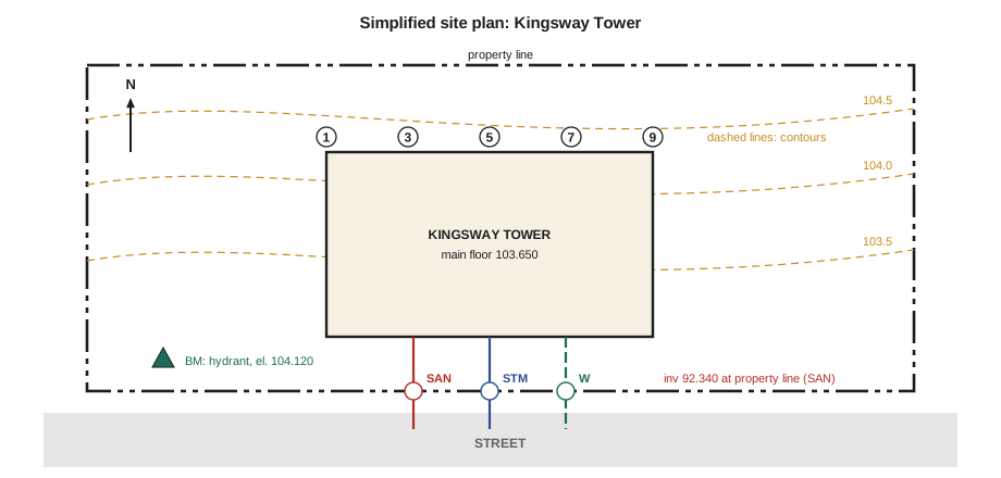
Elevations on the site plan are given in metres. On Kingsway Tower they are geodetic elevations, measured from a national reference close to mean sea level, so the main floor is at about 103.650 rather than at zero. Many architects also use a project datum on the building drawings, in which the main floor is set at 100.000 and everything else is measured from it. The general notes say how the two relate, and mixing them up is a classic and expensive mistake.
For Maya, the site plan matters when the building sewer and water service come in. The sanitary building drain has to leave the building at an invert low enough to slope down to the city sewer connection, and the civil drawings show the invert at the property line and at the connection. Lesson 8 shows how the plumbing drawings pick up that elevation inside the building.
Grid lines: the address system for the building
Every building of any size is laid out on a structural grid: a set of reference lines running in two directions, usually through the centres of the columns. On Kingsway Tower, numbered grid lines 1 to 9 run north-south and lettered grid lines A to F run east-west. The letters I and O are usually skipped so they are not confused with the numbers 1 and 0. Each grid line has a bubble at one or both ends, and the distances between grid lines are dimensioned on the structural and architectural plans.
Grid lines are the master reference for the whole project. They appear on every plan, in every discipline, at the same positions. When the plumbing plan says a cleanout is 600 from grid C and 450 from grid 4, Maya can find the same point on the architectural plan, the structural plan and on the actual slab, where the surveyors have marked the grid lines with paint and nails. A point described as C-4 means where grid C crosses grid 4, which is usually a column.
Grid dimensions on Kingsway Tower are 7200 mm between most numbered lines and 6000 to 8400 mm between the lettered lines. A point between grids is described by its offsets from the nearest grid lines, such as 2400 east of grid 3 and 1200 north of grid C.
Some buildings have angled or curved wings, and then a second set of grid lines, often labelled with primes or decimals such as 3.5 or C.1, is added for intermediate columns or rotated parts of the building. The principle is the same: every point in the building can be described by its distances from two named grid lines.
Floor plans
A floor plan is a horizontal section through a storey, as if the building were sliced about 1.2 m, or about four feet, above the floor and you looked down at what was left. Everything cut by that imaginary plane, mainly walls and columns, is drawn with heavy lines; everything below it, such as floor finishes, counters and plumbing fixtures, with lighter lines; and important things above it, such as beams, bulkheads and openings in the floor above, with dashed lines.
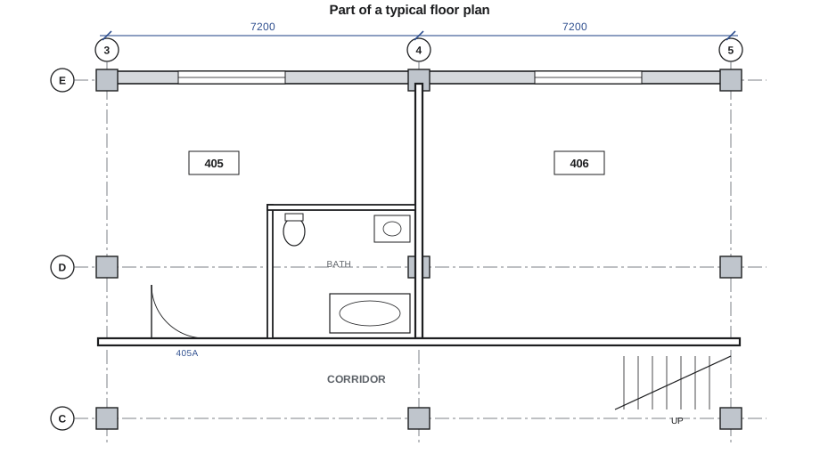
Here is what to look for on any floor plan:
- Walls. Exterior walls are thicker than interior partitions. Many sets tag each wall with a wall type, a symbol that links to a wall type legend showing its layers: studs, insulation, gypsum board, fire rating and sound rating. A fire-rated wall matters to every trade, because every hole made in it must be firestopped.
- Doors. Shown as a line for the door leaf and an arc for its swing, with a door tag that links to the door schedule. The swing tells you which side the hinges are on, which matters for light switches and receptacles.
- Windows. Shown as thin parallel lines within the exterior wall, with a window tag linking to the window schedule or elevations.
- Stairs and elevators. Stairs are drawn with treads, an arrow labelled up or down from the floor shown, and a break line where the cut passes through the stair.
- Room names and numbers. On Kingsway Tower, unit and room numbers start with the floor number: unit 405 is on the fourth floor.
- Fixtures, equipment and millwork. Toilets, tubs, sinks, kitchen cabinets and appliances are drawn in outline so every trade knows where they go.
- Grid lines, dimensions, section marks, elevation markers, keynotes and the north arrow.
A typical floor, one where the layout repeats, may be drawn only once and labelled with all the floors it applies to, such as Levels 3 to 11 Typical Floor Plan. Differences are noted or drawn on separate plans. When you work on one of those floors, confirm that nothing unique applies to it, such as a different unit layout on one level.
Enlarged plans and reflected ceiling plans
Some areas are too crowded to show clearly at 1:100, so the architect draws them again at a larger scale, usually 1:50. Washrooms, kitchens, stairs, elevator lobbies and mechanical rooms commonly get enlarged plans. The enlarged plan governs over the small-scale plan for that area, and its dimensions are the ones to use.
A reflected ceiling plan, or RCP, shows the ceiling: its heights, materials, bulkheads, light fixtures, diffusers, access panels and sprinkler heads. It is drawn as if the floor were a mirror reflecting the ceiling, so that it has the same orientation as the floor plan below it. If the ceiling were drawn as you would see it looking up, everything would be reversed left to right. Sam uses the RCP all the time, because it shows where light fixtures go, and the mechanical trades use it to coordinate diffusers and access panels.
Locating work on a floor plan
Worked problem
Finding a floor drain
The enlarged plan of the fourth-floor laundry room shows a floor drain located 1350 east of grid 6 and 900 south of grid D. The surveyors have marked grid lines 6 and D on the slab. How does Maya mark the drain?
Show solution
- Find the grid marks for 6 and D on the slab, usually painted lines or nails offset from the columns.
- Measure 1350 east from grid 6 along a line parallel to grid D, and make a mark.
- From that mark, measure 900 south, square to grid D, using the 3-4-5 method from TRD-102 to keep the line square.
- Check by measuring back from grid 7 and grid E: the distances should agree with the grid spacing minus the offsets.
Answer: Locate from the grid, square the second measurement, and check from the opposite grid lines before committing.
Checking from the other grid lines catches the common mistake of measuring from the wrong side of a grid mark or reading a dimension from the wrong grid. Surveyors often offset grid marks by a round distance, such as one metre or three feet, so that the marks are not covered by formwork or walls. The offset is written beside the mark, and it must be subtracted or added.
Grid coordinates in code
Drawing software stores every point as coordinates. This program does the same for grid-based locations: it converts a grid intersection plus offsets into coordinates from grid A-1, then finds the distance and direction between two points, which is what you need to run a pipe or conduit between them.
import math, itertools

# spacing between numbered grids (west to east) and lettered grids (south to north); units: mm
num_sp = [7200, 7200, 7200, 7200, 7200, 7200, 7200, 7200]
let_sp = [6000, 8400, 7200, 6000, 7200]
nums = [0] + list(itertools.accumulate(num_sp))
lets = dict(zip("ABCDEF", [0] + list(itertools.accumulate(let_sp))))

def point(grid_num, grid_let, east=0, north=0):
    return nums[grid_num - 1] + east, lets[grid_let] + north

drain = point(6, "D", 1350, -900)
stack = point(5, "C", 3600, 2400)
dx, dy = drain[0] - stack[0], drain[1] - stack[1]
print("drain at", drain, "stack at", stack)
print(f"run {abs(dx)} east-west, {abs(dy)} north-south, straight line {math.hypot(dx, dy):.0f} mm")drain at (37350, 20700) stack at (32400, 16800) run 4950 east-west, 3900 north-south, straight line 6302 mm
Building information models work the same way, with every pipe, wall and column stored by its coordinates. When a model and a printed plan disagree, the grid lines and their dimensions are what you check first.
Partial plans and match lines
Some floors are too big to fit on one sheet at a useful scale. The plan is then split into parts, such as Fourth Floor Plan, Part A and Part B, with a heavy match line drawn where one part ends and the next begins. The match line is labelled with the sheet that continues the plan. When you follow a pipe or a wall across a match line, turn to the referenced sheet and find the same match line there; the grid lines on both sides will match. A key plan in the title block, with the part of the floor shown on this sheet shaded, tells you at a glance which part you are looking at.
Common mistakes
MistakeConfusing geodetic and project elevations.
InsteadRead the general notes to see which datum a drawing uses and how the two relate.
MistakeMeasuring from a surveyor's grid mark without allowing for its offset.
InsteadGrid marks are often offset by a round distance; read the label and adjust.
MistakeUsing the small-scale floor plan where an enlarged plan exists.
InsteadThe enlarged plan governs for its area; use its dimensions.
MistakeReading a reflected ceiling plan as if looking up.
InsteadAn RCP is drawn as a reflection so it lines up with the floor plan below; north is in the same place.
MistakeAssuming a typical floor plan applies to every floor without checking.
InsteadLook for notes or separate plans for floors that differ.
Summary and key terms
- The site plan shows property lines, setbacks, contours, spot elevations, benchmarks and site services.
- Elevations may be geodetic or relative to a project datum; the notes say which.
- Grid lines, lettered in one direction and numbered in the other, are the address system for every sheet.
- Floor plans are horizontal sections about 1.2 m above the floor; cut walls are drawn heavy.
- Enlarged plans show crowded areas at a larger scale and govern over small-scale plans.
- Reflected ceiling plans show the ceiling as a mirror image so they line up with the floor plan.
- Site plan
- A plan of the whole property, showing the building, site work and services.
- Contour line
- A line joining points of equal ground elevation.
- Benchmark
- A fixed point of known elevation used to set other elevations.
- Invert elevation
- The elevation of the inside bottom of a pipe.
- Datum
- The reference level from which elevations are measured.
- Grid line
- A named reference line, usually through column centres, used to locate everything in the building.
- Floor plan
- A horizontal section through a storey, viewed from above.
- Enlarged plan
- A plan of a small area drawn at a larger scale.
- Reflected ceiling plan
- A plan of the ceiling drawn as if reflected in a mirror on the floor.
Practice problems
Work each problem on paper first, then reveal the answer to check.
Which grid letters are usually skipped, and why?
Show answer
I and O, so they are not confused with 1 and 0.
A contour map shows contour lines close together on one side of the site. What does that mean?
Show answer
The ground is steep there.
A fixture is 2400 east of grid 3 and 1200 north of grid C. Grid 3 to 4 is 7200. How far is it from grid 4?
Show answer
7200 - 2400 = 4800 mm west of grid 4.
At roughly what height is a floor plan cut?
Show answer
About 1.2 m above the floor.
Which plan shows the light fixtures in a ceiling?
Show answer
The reflected ceiling plan.
A grid mark on the slab is labelled 1 m offset. What do you do?
Show answer
Measure from the mark and subtract (or add) 1000 mm to work from the true grid line.
Lesson quiz · 5 questions
Score 60% or more to complete this lesson.
Create a free account to save your progress, take quizzes and earn a certificate.