
SMW-310 · Lesson 9 of 12 · 19 min
Field sealing and leakage testing
Air that leaks out of a duct is air the fan paid to move that never reaches the room. Supply leaks starve the far diffusers and push conditioned air into ceilings; return and exhaust leaks pull dust and unconditioned air in. Leaks waste energy, upset balancing and, in a hospital, can move contaminated air where it should not go. That is why specifications call for duct to be sealed to a seal class, and for selected sections to be tested and shown to leak less than an allowable amount. SMW-130 covered the sealing materials and SMW-220 the leakage classes and the formula. This lesson covers how the crew seals in the field, how a leakage test is set up and run, and what to do when a section fails.
At Ashgrove the specification required seal class A on all duct and leakage testing of at least a quarter of the supply and return duct by surface area, chosen by the engineer, at the duct's pressure class. The engineer chose the library supply trunk as one of the test sections, partly because it was the longest run and partly because it was the one the school board would remember if the library was too warm.
Sealing in the field
Seal class A, now the normal requirement, means all transverse joints, longitudinal seams and duct wall penetrations are sealed. Penetrations include screws, rivets, rods passing through the duct, damper shafts, test holes and instrument connections. Most joints are sealed as they are made: gasket in flanged joints, mastic on slip joints and round joints before assembly, or gasketed fittings. Seams sealed in the shop arrive ready. In the field, the crew seals anything it adds or disturbs: field-cut takeoffs, screw heads near joints, corner pieces, damper shafts and any gaps the inspection finds.
Good sealing depends on preparation. The surface must be clean, dry and free of oil; mastic will not stick to a dusty or oily sheet, and tape will peel. Mastic is applied with a brush or gun in the thickness the manufacturer specifies, worked into the joint and over screw heads, and given time to cure before the duct is tested or insulated. Cold weather slows curing; some sealants have a minimum application temperature, which matters on roofs and in unheated buildings in a Halifax or Cleveland winter. Tapes must be the type listed for duct sealing and applied to clean metal with firm pressure.
Keelson's crews seal before testing and test before insulating. Sealing after a failed test is possible but much slower, because the leaks have to be found first. Sean's rule for Kai was to look at every joint as if the test had already failed and he had to guess where.
What a leakage test measures
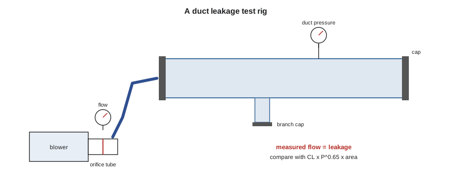
A leakage test pressurizes a closed section of duct, or depressurizes it for return and exhaust duct, and measures the airflow needed to hold the test pressure. Because the section is closed, every bit of that airflow is leaking out. The measured leakage is compared with an allowable leakage worked out from the section's surface area, the test pressure and the leakage class in the specification. SMACNA's HVAC Air Duct Leakage Test Manual describes the equipment and procedures most specifications refer to.
The allowable leakage per unit of duct surface follows the relationship used in SMW-220: F equals the leakage class times the test pressure raised to the power 0.65. In US units, F is in cubic feet per minute per 100 square feet of duct surface and the pressure is in inches of water. Leakage class 4, common in specifications for seal class A rectangular duct, allows four times the 0.65 power of the pressure. Lower classes are tighter. Round duct is often held to a lower class than rectangular, because it has fewer seams and should leak less.
Setting up the test
The test section is chosen and agreed with the engineer or commissioning agent, and its surface area is worked out from the shop drawings: the perimeter times the length of each piece, plus fittings and branches up to the caps. Every opening is capped with sealed plates, plugs or inflatable bladders. Dampers in the section are opened if the test includes the duct beyond them, or the section ends at a damper with the damper blanked. The rig is connected through a cap with a sealed fitting, and a separate pressure tap is installed in the duct away from the rig connection to read the duct pressure, so the reading is not upset by the air jet from the hose.
The test pressure is normally the duct's pressure class, or a value the specification gives, and never more than the duct was built for: over-pressurizing light-gauge duct can bulge panels and blow joints. The test rig must be calibrated, and the flow element and manometers read within their ranges. Keelson's rig used an orifice tube with a calibration chart, so the measured pressure difference across the orifice gave the flow directly.
Running the test
With everything capped and sealed and the sealant cured, the operator starts the blower slowly and raises the duct pressure to the test value, watching the duct for movement and listening for leaks. Once the pressure is steady, the operator reads the orifice pressure difference and the duct pressure, converts the reading to flow, and compares it with the allowable. Many specifications also require the pressure to be held for a few minutes with the flow steady. The engineer or commissioning agent often witnesses the test and signs the report.
Kai ran the numbers for the library supply test section before Sean booked the commissioning agent, so the crew knew what flow it had to beat. The section included trunk T1, T2 and T3, the plenum and the first metre of each branch to its cap.
# Allowable and measured leakage for a test section
area_sqft = 43.0 * 10.764          # duct surface area of the section, square feet
p_inwg = 500 / 249.1                # test pressure, inches of water
cl = 4                         # leakage class from the specification
f = cl * p_inwg ** 0.65        # allowable leakage, cfm per 100 square feet
allow_cfm = f * area_sqft / 100
allow_ls = allow_cfm * 0.4719
print(f"section area 43.0 m2 at 500 Pa")
measured = 7.3              # flow read from the rig at the test pressure, L/s
print(f"allowable leakage {allow_ls:.1f} L/s for the section")
print(f"measured leakage {measured} L/s: {100 * measured / allow_ls:.0f} percent of the allowable")
print("PASS" if measured <= allow_ls else "FAIL: find and seal the leaks, then retest")
share = measured / 2400 * 100
print(f"that is {share:.2f} percent of the system design airflow")section area 43.0 m2 at 500 Pa allowable leakage 13.7 L/s for the section measured leakage 7.3 L/s: 53 percent of the allowable PASS that is 0.30 percent of the system design airflow
The section allowed a little over twice what the crew expected to measure, so Sean was confident, but he also knew a single unsealed corner piece could use up the whole allowance. The measured leakage, well under one percent of the system airflow, shows how tight a well-sealed flanged system can be.
When a section fails
If the measured leakage is over the allowable, the crew holds the section at pressure and hunts for the leaks. Large leaks can be heard and felt. Smaller ones show up with soapy water brushed on joints, which bubbles, or with a theatrical smoke puffer or a smoke pencil, which shows air streaming out. Common leak points are corner pieces of flanged joints, unsealed screws, field-cut takeoffs, damper shafts, access door gaskets, test caps and the rig connection itself. The leaks are sealed, the sealant is allowed to cure, and the section is retested. A failed test is recorded, with what was found and fixed, alongside the passing retest.
On the first test of a corridor return section at Ashgrove, the rig could not reach the test pressure. The cause turned out to be a cap on a return grille branch that had come loose when someone leaned on it: the duct was fine. Sean's lesson for Kai was to check the caps and the rig connection first, before blaming the duct.
Codes, specifications and reports
Leakage testing requirements come mainly from the project specification, often based on SMACNA's test manual and the energy code. Nova Scotia's energy code, based on the National Energy Code of Canada for Buildings, requires duct to be sealed, and many public and institutional specifications go further and require a percentage of the duct to be tested. Health care specifications, such as Eastgate's, often require testing of all supply duct serving critical areas.
The test report records the project, the section and its drawing reference, the duct pressure class and seal class, the surface area, the test pressure, the leakage class, the allowable and measured leakage, the rig's calibration, the date, and the names and signatures of the tester and the witness. It goes into the closeout documents and is often the first thing a balancing contractor asks for when a system will not deliver its design airflow.
Worked problem
Working out the allowable leakage
A rectangular supply section has 300 square feet of surface and is tested at 2 inches of water with leakage class 4. What is the allowable leakage? Give the answer in L/s as well.
Show solution
- F = 4 × 2^0.65 = 4 × 1.569 = 6.28 cfm per 100 square feet.
- Allowable = 6.28 × 300 ÷ 100 = 18.8 cfm.
- In SI: 18.8 × 0.4719 = 8.9 L/s.
Answer: About 18.8 cfm, or 8.9 L/s, for the whole section.
Planning tests on a real job
Testing takes time, so it has to be planned like any other work. Sean picked the test sections with the commissioning agent early, so the crew could build in test points: a capped end on each section, a hole for the rig connection in a straight part of the duct, and a place to put the rig on the floor below with power for the blower. Test sections were sized to suit the rig: Keelson's rig could hold about 60 L/s (130 cfm) at the higher test pressures, so a long main was tested in two parts rather than one if the expected leakage approached that. Sections were tested as soon as their sealant had cured, not at the end of the job, so a failed section could be fixed before the insulators and the ceiling contractor arrived.
Return and exhaust sections are tested under negative pressure, with the rig arranged to draw air out of the duct, because those ducts operate below atmospheric pressure and their joints are pulled inward. Some specifications allow testing positive for convenience; the crew follows what the specification says. Low-pressure duct on a small job may not need a measured test at all; the specification may require only a visual inspection of sealing, or a smoke test in which theatrical smoke is blown into the duct while the crew looks for wisps at the joints.
The rig is also a measuring instrument and is treated like one. Keelson's orifice tube had a calibration certificate, the manometers were checked against a reference each season, and the hoses were inspected for cracks, because a leaking hose between the orifice and the manometer gives a wrong reading. A test is only as good as the instrument that measured it.
The test also checks the duct's construction. A section that holds its pressure only with large flow, or whose panels move visibly under pressure, may have a construction problem rather than a sealing problem, such as missing reinforcement or an undersized gauge. Kai learned to watch the duct as the pressure came up, not just the manometer.
Common mistakes
MistakeTesting before the sealant has cured.
InsteadAllow the cure time the manufacturer gives, longer in the cold.
MistakeReading duct pressure at the rig connection.
InsteadUse a separate pressure tap away from the hose connection.
MistakeTesting light duct above its pressure class.
InsteadTest at the specified pressure, never above the duct's class.
MistakeBlaming the duct when the rig cannot reach pressure.
InsteadCheck the caps, plugs and rig connection first.
MistakeInsulating before the test is witnessed.
InsteadTest, record and get sign-off, then insulate.
Summary and key terms
- Seal class A requires all joints, seams and penetrations to be sealed.
- Surfaces must be clean and dry, and sealant cured, before testing.
- A leakage test measures the airflow needed to hold a closed section at the test pressure.
- Allowable leakage F = CL × P^0.65 per 100 square feet, times the section area.
- Failed sections are searched with sound, soap or smoke, sealed and retested.
- Reports record the section, area, pressure, class, allowable and measured leakage and the witness.
- Seal class A
- Sealing of all transverse joints, longitudinal seams and duct wall penetrations.
- Leakage class
- A number that sets the allowable leakage rate for a given pressure.
- Test pressure
- The static pressure at which a section is tested, usually its pressure class.
- Orifice tube
- A calibrated flow measuring device in the test rig.
- Test section
- A capped length of duct chosen for leakage testing.
- Commissioning agent
- An independent party who checks that systems are installed and work as designed.
Practice problems
Work each problem on paper first, then reveal the answer to check.
A section of 25 m² is tested at 250 Pa (1.0 in) with class 4. What is the allowable in L/s?
Show answer
F = 4 × 1.0^0.65 = 4 cfm per 100 sq ft; area 269 sq ft; allowable 10.8 cfm = 5.1 L/s.
Where are leaks most often found on flanged duct?
Show answer
At the corner pieces, unsealed screws, takeoffs, damper shafts and access doors.
Why is the duct pressure read away from the rig connection?
Show answer
The air jet from the hose upsets the reading near the connection.
What should be checked first when the rig cannot reach test pressure?
Show answer
The caps, plugs and rig connection.
Lesson quiz · 5 questions
Score 60% or more to complete this lesson.
Create a free account to save your progress, take quizzes and earn a certificate.