
SMW-310 · Lesson 12 of 12 · 19 min
Capstone: installing and testing the Ashgrove library system
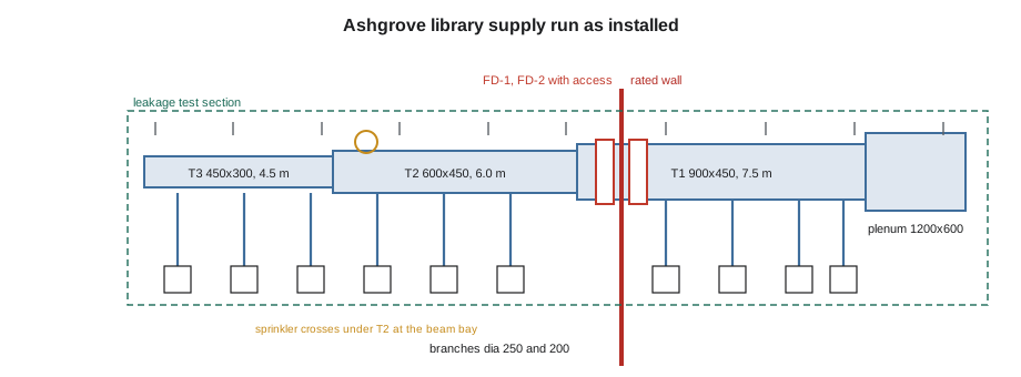
The library supply run is where this course comes together. In SMW-220, Kai helped fabricate it: a plenum, three stepped trunks, ten round branches, two fire dampers with access doors and the volume dampers and diffusers. In this capstone he helps install it, from the first chalk line on the library floor to the signed leakage test report and the handover to the insulator and the balancer. Sean made Kai the crew's recorder for the job, which meant he kept the hanger log, the damper checklist, the test data and the punch list, and wrote the closeout notes at the end.
The work was done in the first two weeks of August, after the corridor mains and before the ceiling contractor came back to close the library ceiling. Aggie was lead hand, Sean ran the crew and the coordination, and a second apprentice joined for the lifting days.
Before the first hanger: checks and coordination
Kai started with the documents: the reviewed shop drawings from Lin, the design drawings, the air terminal schedule, the damper submittals with the manufacturer's installation instructions, the specification sections for duct, accessories and testing, and the answer to his request for information about the cast iron drain under trunk T2. He made a one-page job sheet listing every item with its tag, size and location, and marked the inspection points: dampers before the wall was closed, sealing before the test, the test before insulation.
At the Monday coordination meeting with the general contractor and the other trades, Sean confirmed the order of work in the library ceiling: duct first, then the sprinkler branch lines, then the electricians' cable tray and fixtures. The sprinkler fitter wanted to run a branch line through the bay where Kai's fit check had shown less than a hundred millimetres (four inches) to spare under the beam, so they agreed that the fitter would cross under the duct at that bay, with Lin's bottom-of-duct elevation marked on the beam as the limit.
Layout
Aggie re-established the library gridlines from the column centres, checked them against the end walls, and set the rotating laser on the benchmark line the general contractor had snapped. Kai snapped the trunk centreline on the floor, measured every hanger point from the gridline, marked the branch centrelines from the reflected ceiling plan, and transferred the points to the slab and beams with the plumb-point laser. The check against the reflected ceiling plan caught the return grille positions that had moved half a tile, as lesson 3 described, before any branch was cut.
Supports and anchors
The trunks hung on angle trapezes from wedge anchors in the old slab and from wraparound beam clamps on the steel beams. Before drilling, the crew had the slab checked for embedded services where the drawings were uncertain, and moved any hole that hit rebar instead of drilling through it. Every anchor was set with a torque wrench and recorded on the hanger log with its location, size and torque. The anchor near the new riser opening, checked in lesson 5, was logged with its edge distance and the note that it had been checked against the manufacturer's edge table.
Kai worked out the hangers for the whole run from the lengths, the chart spacing and the extra hangers at joints, branches and dampers, then checked the count against the hanger points on the floor.
# Capstone summary: hangers, test section and result (illustrative values)
import math
runs = [('plenum', 1.2, 3.0, 1), ('T1', 7.5, 3.0, 3), ('T2', 6.0, 3.0, 3), ('T3', 4.5, 3.0, 2)]          # (trunk, length m, chart spacing m, extra hangers at joints, dampers, branches)
total = 0
for name, length, spacing, extra in runs:
    n = math.ceil(length / spacing) + 1 + extra
    total += n
    print(f"{name}: {n} trapezes")
print(f"trunk trapezes in total: {total}; anchors {2 * total} (two rods each)")
area = 43.0 * 10.764          # test section surface area, square feet
p = 500 / 249.1                # test pressure, in w.g.
allow = 4 * p ** 0.65 * area / 100
first, retest = 15.9, 7.3        # measured, L/s
allow_u = allow * 0.4719
print(f"allowable {allow_u:.1f} L/s")
print(f"first test {first} L/s: {'pass' if first <= allow_u else 'fail'}; retest {retest} L/s: {'pass' if retest <= allow_u else 'fail'} ({100 * retest / allow_u:.0f} percent)")plenum: 3 trapezes T1: 7 trapezes T2: 6 trapezes T3: 5 trapezes trunk trapezes in total: 21; anchors 42 (two rods each) allowable 13.7 L/s first test 15.9 L/s: fail; retest 7.3 L/s: pass (53 percent)
The count matched the floor marks. The extra hangers were at the T1 to T2 and T2 to T3 transitions, both sides of the fire damper sleeves, the vaned elbow under the beam and the heaviest branch takeoffs. The first test result in the script is the story of the next sections.
Hanging, joining and the fire dampers
The plenum and trunk T1 went up on the first day, as lesson 1's progress check described. Aggie hung the first T1 section dead to the laser and the layout, and the crew hung each following section to the previous one, checking against the laser every third section. The TDC joints were gasketed, corner-bolted and clipped to the field rule from lesson 7, and the T2 offset under the cast iron drain went in as the RFI answer allowed.
The fire dampers went into the rated wall between the library and the corridor on the second day, in rough openings the drywall contractor had framed to Kai's sizes from lesson 8. Kai checked each installation against the manufacturer's instructions with a printed copy in hand: sleeve gauge, retaining angles on both sides fastened to the sleeve only, the clearance gap left open under the angles as the listing required, breakaway slip-and-drive connections to the duct, and independent hangers within the distance allowed on each side. On FD-2 he found one retaining angle screwed to a stud through the board: the drywall finisher had added screws to hold the angle while taping. The screws came out, the holes in the angle were left, and the finisher's foreman was shown the instruction sheet. The inspector passed both dampers the next day.
The round branches went in on the third and fourth days. Each spin-in was cut in at the branch centreline marked from the reflected ceiling plan, sealed, and fitted with its volume damper and standoff quadrant. The final connections to the library diffusers were short flexible ducts, which the specification allowed up to 1.5 m (5 ft). At SD-4, Kai found the second apprentice had left a flex about 300 mm (a foot) long and pushed together. He had it cut to length so it was fully extended, the core fastened and sealed to the collar, and the jacket fastened separately, as lesson 10 described.
Sealing and the leakage test
Before testing, Kai walked the run with a flashlight and the job sheet, checking every joint, corner, screw near a joint, takeoff and damper shaft, and the crew sealed what he marked. The sealant was given its full cure time; the library was air-conditioned by then, so the cure was not slowed by cold. The test section, agreed with the commissioning agent, ran from the plenum to the caps on each branch about a metre (three feet) past its takeoff, including both fire dampers, which were open.
The first test failed. The rig held the test pressure only at about twice the expected flow, just over the allowable. With the section pressurized, the crew found three leaks with soapy water and a smoke pencil: a corner piece on a T1 joint where the gasket had been butted instead of lapped, a test cap on a branch that had not been fully sealed, and an access door on FD-1 whose gasket had a gap at a corner. The corner was resealed with mastic, the cap was re-taped, and the access door gasket was replaced. The next morning the retest passed at about half the allowable, witnessed by the commissioning agent, and the report was signed.
| Item | Value |
|---|---|
| Test section | Plenum, T1 to T3, both fire dampers, branch stubs to caps |
| Pressure class and seal class | +500 Pa (+2 in w.g.) and seal class A |
| Surface area | 43.0 m² (463 sq ft) |
| Test pressure and leakage class | 500 Pa (2.0 in w.g.), class 4 |
| Allowable leakage | 13.7 L/s (29.1 cfm) |
| First test | 15.9 L/s (33.7 cfm): fail; three leaks found and sealed |
| Retest | 7.3 L/s (15.5 cfm): pass, about 53 percent of the allowable, witnessed |
Connections, protection and handover
The connection to the corridor main and the new rooftop unit's supply plenum was made on the planned Saturday shutdown from lesson 11, with the fittings staged the day before. The flexible connector at the unit was aligned and left with slight slack. After the test, the crew capped all branch ends again, cleaned the duct exterior, and handed the run to the insulator with a marked-up drawing showing the areas inspected and tested. Two days later the ceiling contractor closed the grid, leaving the tiles under the fire dampers and volume damper quadrants labelled for access.
Kai's closeout package for the library included the hanger log, the anchor torque records, the damper checklist with photos of both installations, the signed test report including the failed first test and what was found, the RFI answer for the T2 offset, and a redlined drawing showing the as-built routes, the flattened section and the damper and access door positions, for the record drawings. The balancing contractor started the following week and asked first for the test report and the damper locations.
What Kai took from the job
Sean asked Kai to write three lessons from the library for the crew's next job, the way Walt had asked him after the SMW-220 fabrication. Kai wrote: check every listed installation against the manufacturer's sheet, because other trades will change it without knowing it matters; lap the gasket at every corner and seal every test cap as carefully as the duct, because the first test usually fails on the small things; and put the bottom-of-duct elevation on the beam where another trade wants the same space, because a number on the structure settles arguments a drawing does not. Sean added the first two to Keelson's field checklist and sent the third to Lin, who added beam tags to the coordination drawing template.
Worked problem
Was the first test really a failure?
The allowable was 13.7 L/s and the first test measured 15.9 L/s. By how much did it fail, and why did the crew retest instead of arguing for a pass?
Show solution
- 15.9 ÷ 13.7 = 1.16: about 16 percent over the allowable.
- The specification sets a limit, not a target, and the commissioning agent signs only against the limit.
- The leaks were easy to find and fix, and the retest showed the duct itself was well within the allowable.
Answer: It failed by about 16 percent. Finding and sealing the three leaks took an hour; the retest passed at about half the allowable.
Measuring the job against the plan
Kai also compared the actual hours with the estimate from lesson 1. The library run, from layout to handover, took about the estimated crew-hours plus a day: the extra came from the FD-2 correction, the failed first test and the T2 offset, each small on its own. Sean used the comparison to adjust Keelson's labour units for crowded retrofit ceilings, so the next school retrofit would be priced on real numbers. Field data like this is how a contractor's estimates stay honest.
Common mistakes
MistakeTrusting that a fire damper installation stays as installed.
InsteadCheck it again before the inspection; other trades may alter it.
MistakeSealing test caps less carefully than the duct.
InsteadA leaking cap fails the test as surely as a leaking joint.
MistakeLeaving flex longer than needed.
InsteadCut flex so it is fully extended.
MistakeLeaving the failed test out of the report.
InsteadRecord failures, causes and fixes with the passing retest.
MistakeHanding over without as-built markups.
InsteadRedline routes, changes and access points for the record drawings.
Summary and key terms
- The capstone ran from documents and coordination through layout, supports, hanging, dampers, sealing, testing, connections and handover.
- Layout from the building's references and the reflected ceiling plan avoided rework on branches and grilles.
- Every listed damper installation was checked against the manufacturer's instructions, and a change by another trade was caught.
- The first leakage test failed on small details: a butted gasket, a cap and an access door; the retest passed at about half the allowable.
- Records of anchors, dampers, tests and as-built changes form the closeout package for the owner and balancer.
- Field lessons go back into the company's checklists and drawing standards.
- Closeout package
- The records handed to the owner at the end of the work: logs, tests, checklists and as-built information.
- Redline
- A marked-up drawing showing how the work was actually built.
- Punch list
- A list of items to fix or complete before the work is accepted.
- Witnessed test
- A test observed and signed by the engineer, commissioning agent or inspector.
- Hanger log
- A record of each hanger and anchor: location, type, size and torque.
- Record drawings
- The final drawings showing the building as built.
Practice problems
Work each problem on paper first, then reveal the answer to check.
A trunk is 7.5 m long with a chart spacing of 3.0 m and three extra hangers. How many trapezes?
Show answer
ceil(7.5 ÷ 3.0) + 1 + 3 = 3 + 1 + 3 = 7.
Name three things found on the first library leakage test.
Show answer
A butted gasket at a flange corner, an unsealed test cap and a damper access door gasket gap.
What did Kai find on fire damper FD-2?
Show answer
A retaining angle screwed to a stud by the drywall finisher; the screws were removed.
What does the balancing contractor usually ask for first?
Show answer
The leakage test report and the damper locations.
Lesson quiz · 5 questions
Score 60% or more to complete this lesson.
Create a free account to save your progress, take quizzes and earn a certificate.