
SMW-310 · Lesson 2 of 12 · 20 min
Reading HVAC drawings and specifications
A field installer spends as much time reading as lifting. Before a single hanger goes up, the crew has to know where the duct goes, how big it is, how high it sits, what it connects to, what accessories it carries and what the specification says about materials, sealing and testing. That information is spread across the mechanical drawings, the architectural and structural drawings, the specification, the shop drawings and the answers to requests for information. This lesson covers how to read them together and how to spot the problems before they become mistakes in the ceiling.
Kai had read shop drawings for two years on the fabrication floor, where every piece already had its size and length worked out. On Sean's crew he had to work from the design drawings as well, and to read them the way the foreman does: as a set of decisions made by an engineer who never stood in the Ashgrove library ceiling.
The drawing set
A building's drawings are grouped by discipline, each with its own prefix: A for architectural, S for structural, M for mechanical, P for plumbing, E for electrical, FP for fire protection. The mechanical set usually starts with a legend sheet of symbols and abbreviations and the general notes, then plans of each floor for duct and for piping, then roof plans, sections and enlarged plans of crowded areas, then details, and finally schedules of equipment and air terminals. Demolition plans come first on a renovation and show what has to be removed.
The duct plan is the main sheet for the crew. It shows each duct as a double line drawn to scale, with its size written beside it, and the air terminals, dampers, access doors and equipment in their places. Supply duct, return duct and exhaust duct are often shown with different line types or labels, and the direction of airflow is marked with arrows. The plan is a view looking down, so a duct size such as 600 × 450 (24 × 18) means the side seen in plan, the width, first, and the depth second. Round duct is shown with a diameter symbol, such as Ø250 (10 in Ø).
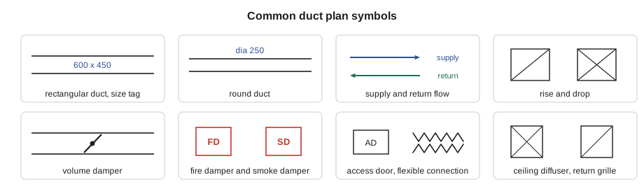
Reading duct plans
Read a duct plan from the source outward: start at the air handler or fan, follow the main, note every size change, branch, fitting and accessory, and end at each terminal. Several things deserve attention on every run.
- Size changes. A size tag applies until the next tag. Transitions are often drawn as a short taper; the shop drawing shows the exact fitting.
- Rises and drops. A change in elevation is shown with a symbol, often a rectangle with a diagonal line for a rise and a crossed one for a drop, and the elevations are given in a note or on a section.
- Accessories. Volume dampers, fire dampers, smoke dampers and access doors are shown by symbol and tag. A fire damper symbol tells you there is a fire separation; check the architectural plan for its rating.
- Terminals. Each diffuser, register or grille has a tag that points to the air terminal schedule, which gives its type, size, neck size and airflow.
- Notes. Keyed notes, the small numbers in hexagons or circles, point to text on the same sheet. They often hold the most important instructions on the sheet.
The architectural reflected ceiling plan shows the ceiling grid, lights, sprinkler heads and air terminals as seen from below, as if the ceiling were a mirror. The diffuser positions on the mechanical plan have to agree with it. Where they disagree, the reflected ceiling plan usually wins for location, because the architect controls the ceiling layout, but the disagreement is still raised as a question.
Sections, elevations and details
Plans show where; sections show how high. A section cuts through the building and shows the structure, the ceiling and the services in their vertical positions. On a crowded job, sections through the corridors and mechanical rooms are the most useful sheets the crew has, because they show which service is on top. Elevations are given either as height above the finished floor or as absolute elevations tied to a site datum. Duct elevations are usually given to the bottom of the duct, abbreviated BOD, sometimes to the centreline, and occasionally to the top; the legend says which.
Details show how things are built: hanger types, fire damper installations, roof curbs, flexible connections, seismic bracing, duct penetrations through walls and roofs. Many specifications refer to standard details from SMACNA, from the damper manufacturer or from the authority having jurisdiction. When the detail and the plan disagree, the crew does not choose; the foreman asks.
Schedules
Schedules are tables that list equipment and terminals with their data. The equipment schedule gives each air handler and fan its airflow, static pressure, motor and connection sizes. The air terminal schedule gives each diffuser and grille its type, face size, neck size, pattern and design airflow. Damper schedules list fire, smoke and combination dampers with their ratings, sizes and actuators. The crew needs the neck sizes to connect branches and the airflows to check that the branch sizes look sensible; the balancer later uses the same airflows to set the dampers.
| Tag | Type | Face size | Neck | Pattern | Design airflow |
|---|---|---|---|---|---|
| SD-1 | square plaque diffuser | 600 × 600 (24 × 24) | Ø250 (10 in) | 4-way | 250 L/s (530 cfm) |
| SD-2 | square plaque diffuser | 600 × 600 (24 × 24) | Ø200 (8 in) | 4-way | 175 L/s (370 cfm) |
| RG-1 | egg-crate return grille | 600 × 600 (24 × 24) | 550 × 550 (22 × 22) | n/a | 600 L/s (1270 cfm) |
| LD-1 | linear slot diffuser, 2 slot | 1200 long (48 in long) | Ø200 (8 in) | 1-way | 150 L/s (320 cfm) |
The specification
The drawings show quantity and arrangement; the specification describes quality and method. North American specifications are usually organized by the MasterFormat system, in which HVAC is Division 23. The sections that matter most to the duct crew are the ones on metal ducts, air duct accessories, air terminals, testing, adjusting and balancing, and HVAC insulation. Each section has three parts: general requirements such as submittals and quality assurance, products, and execution, which tells the installer how to install, seal, test and clean.
On the Ashgrove job the specification was written in the National Master Specification format used on many public jobs in Canada. Its metal duct section called for duct built to the SMACNA construction standards for the pressure classes on the drawings, seal class A on all supply, return and exhaust duct, leakage testing of selected sections, clean duct practices with capped openings, and hangers per SMACNA. Its accessories section required fire dampers listed to the Canadian fire damper standard, installed per the manufacturer's instructions with access doors at every fusible link.
Specifications use precise words. "Shall" is mandatory. "Provide" means furnish and install. "As indicated" means as shown on the drawings. "Or approved equal" means a substitute is possible only with the engineer's written approval. The crew follows the specification even when the shop's usual practice is different; if the specification is stricter, it wins, and if it seems wrong, the foreman asks.
Shop drawings, submittals and RFIs
Before fabrication, the contractor prepares shop drawings and submits them with product data for the engineer's review. Lin's shop drawings for Ashgrove showed every piece with its exact size, length, gauge, joints and reinforcement, the elevations of the bottom of the duct, the hanger points and the damper locations, all coordinated with the other trades. The engineer reviewed them for general conformance with the design, and the stamped review came back marked reviewed, reviewed as noted, or revise and resubmit. Field installation follows the reviewed shop drawings, which are more detailed than the design drawings but must agree with them.
A request for information is a formal written question to the designer. A good RFI states the problem, references the drawings and specification, proposes a solution and says when an answer is needed to avoid delay. Kai drafted his first one for Ashgrove when he found that the library section showed trunk T2 at the same height as the cast iron drain Lin had found on the walk-through. Sean edited it and sent it through the general contractor. The answer allowed a 150 mm (6 in) offset with the duct flattened to keep its area, and it became part of the contract documents.
Checking the fit: will it go?
The most common field check is whether a duct fits in the space between the ceiling and the structure. The space must hold the duct, its insulation, its hanger hardware or trapeze, and the clearance the installer needs to make joints, plus any service crossing above or below it. A duct that only just fits on paper rarely fits in the field.
Kai checked trunk T2 at its tightest point, under a steel beam in the library, before Lin released it to the shop. The dimensions came from the section, the walk-through measurements and the insulation specification.
# Will the duct fit between the beam and the ceiling? (all dimensions in mm)
beam_bottom = 3350      # underside of beam above finished floor
ceiling = 2700          # finished ceiling height
grid_space = 150       # space needed above the ceiling for the grid and lights
duct_depth = 450       # outside depth of the duct
insulation = 25       # external wrap, top and bottom
trapeze = 40          # angle trapeze under the duct
clearance = 50        # working room above the duct for joints and hangers
needed = duct_depth + 2 * insulation + trapeze + clearance
available = beam_bottom - (ceiling + grid_space)
print(f"space needed {needed:.0f} mm, space available {available:.0f} mm")
spare = available - needed
if spare >= 0:
    print(f"fits with {spare:.0f} mm to spare")
    bod = ceiling + grid_space + trapeze + insulation
    print(f"set the bottom of the duct at {bod:.0f} mm above the floor")
else:
print(f"does not fit: short by {-spare:.0f} mm; flatten the duct or reroute")space needed 590 mm, space available 500 mm does not fit: short by 90 mm; flatten the duct or reroute
The duct fitted, but with less than a hundred millimetres (four inches) to spare. Sean asked Lin to show the bottom-of-duct elevation on the shop drawing at that beam and to tag the spot for the sprinkler fitter, who planned to run a branch line through the same bay.
Worked problem
Reading a size tag and a schedule together
Diffuser SD-1 in the library is fed from trunk T3, 450 × 300. The schedule gives SD-1 a Ø250 neck and 250 L/s. What branch size should the crew expect, and what accessory is normally in the branch?
Show solution
- The branch normally matches the diffuser neck: Ø250 round.
- The plan shows a volume damper symbol near the takeoff; the specification calls for a balancing damper in each branch with an accessible quadrant.
- Check the velocity: 0.250 m³/s ÷ (π × 0.125²) = 5.1 m/s, matching the SMW-220 sizing.
Answer: A Ø250 branch with a volume damper at the takeoff, connected to the diffuser neck.
Revisions, bulletins and the drawing log
Drawings change during a job. The engineer issues revised sheets, bulletins and sketches, and answers to requests for information may change a detail or a size. Each revised sheet carries a revision number and date in its title block and usually a cloud around the changed area with a triangle tag. A crew that works from an old sheet installs yesterday's design. Keelson keeps a drawing log for each job listing every sheet, its current revision and the date it was received, and the foreman replaces superseded sheets in the field set the day new ones arrive, marking the old ones void or removing them. On tablets, the crew works from the current set synced from the office, but Sean still checked the revision block before starting each area.
At Ashgrove, the third mechanical revision moved two library diffusers to suit the new light fixtures. The change was clouded on sheet M-201 and listed in the bulletin. Because Kai checked the revision log before laying out the branches, the spin-ins went in at the new positions; the old positions would have put two diffusers a full tile from the new lights and needed rework after the ceiling was installed.
Common mistakes
MistakeReading the duct size backwards.
InsteadOn a plan, the first number is the width seen in plan, the second is the depth.
MistakeWorking from the design drawings when reviewed shop drawings exist.
InsteadInstall from the reviewed shop drawings, and check that they agree with the design.
MistakeIgnoring keyed notes.
InsteadRead every keyed note; they often carry the key instructions.
MistakeChoosing between conflicting documents on your own.
InsteadRaise a request for information and get a written answer.
MistakeAssuming the bottom-of-duct elevation is the centreline.
InsteadCheck the legend for how elevations are given.
Summary and key terms
- The duct plan shows routes, sizes and accessories; sections and elevations show heights.
- Duct sizes are given width first, as seen in plan; round sizes use the diameter symbol.
- Schedules list equipment, terminals and dampers with sizes and airflows.
- The specification sets materials, methods, sealing, testing and cleanliness; Division 23 covers HVAC.
- Reviewed shop drawings guide installation; RFIs resolve conflicts in writing.
- Always check that the duct, insulation, hangers and working room fit the space.
- Reflected ceiling plan
- An architectural plan of the ceiling as seen from below, showing grid, lights and air terminals.
- BOD
- Bottom of duct; the usual reference for a duct elevation.
- Keyed note
- A numbered note on a drawing that refers to text on the same sheet.
- Air terminal schedule
- A table of diffusers, registers and grilles with their sizes and design airflows.
- Shop drawing
- A detailed drawing prepared by the contractor showing exactly how the work will be made and installed.
- Submittal
- Drawings and product data sent to the designer for review before fabrication or purchase.
Practice problems
Work each problem on paper first, then reveal the answer to check.
A plan shows a duct tagged 750 × 300. Which dimension is the depth?
Show answer
300 mm; the second number is the depth.
The space between ceiling grid and beam is 520 mm. The duct is 400 deep with 25 mm wrap top and bottom and a 40 mm trapeze. Is there 50 mm of working room?
Show answer
400 + 50 + 40 = 490 mm, leaving 30 mm: not enough. Flatten the duct or reroute.
What does "or approved equal" mean in a specification?
Show answer
A substitute is allowed only with the engineer's written approval.
Where would you look to find a diffuser's neck size?
Show answer
In the air terminal schedule, using the tag on the plan.
Lesson quiz · 5 questions
Score 60% or more to complete this lesson.
Create a free account to save your progress, take quizzes and earn a certificate.