
SMW-220 · Lesson 4 of 12 · 19 min
Reinforcement of rectangular duct
On a small duct, the sheet and the transverse joints are enough. On a larger one, the sides between joints would bulge out under positive pressure or pull in under suction, and the duct needs reinforcement: stiff members wrapped around it or fixed across it at intervals along its length. SMW-130 left the detailed reinforcement rules to this course, because they belong with the gauge and joint choices of a whole duct. This lesson explains why duct sides need reinforcing, how the standard's tables tie gauge, joint spacing and reinforcement together, which members are used and how they are fixed, and when tie rods are needed. It follows Kai through the reinforcement of the largest piece at Ashgrove, the plenum box at the rooftop unit, and a section of Eastgate's riser.
Why reinforce
Think of a duct side as a long, flat strip of sheet held at its two edges by the corner seams. Pressure acts on its whole face. Between the joints at each end of a section, nothing stops it from bowing except its own stiffness, which for thin sheet is very small. The wider the side, the further it bows; the higher the pressure, the further again. A bowed side rattles, drums and loads the seams at the corners, and if it bows far enough it can split a seam, pull a joint apart or, on a negative duct, cave in.
Reinforcement works by dividing the length of each side into shorter spans. A stiff member wrapped around the duct, fixed to each side, holds the sheet at that line just as a joint does. Now the side spans only from one member to the next, and the bowing between them is small. The heavier the sheet, the further apart the members can be; the higher the pressure or the wider the side, the closer they must be and the stiffer each member must be.
How the tables work
The standard's rectangular duct tables combine three choices for each duct width and pressure class: the sheet gauge, the spacing of reinforcement along the duct, and the stiffness of the reinforcement members. For each combination they give a minimum rating for the transverse joints and the intermediate reinforcement. Each table row offers more than one way to meet the same requirement: a lighter gauge with reinforcement closer together, or a heavier gauge with members further apart, or for small ducts a heavy enough gauge with no intermediate reinforcement at all.
Two kinds of reinforcement appear in the tables. Joint reinforcement is the stiffness of the transverse joint itself, at the end of each section. Intermediate reinforcement is an added member between the joints, used when the spacing the table requires is shorter than the section length. If the table says reinforcement every 1.5 m and the sections are 1.5 m long, the joints alone do the job, provided they have the rating the table requires. If the table says every 0.9 m on 1.5 m sections, one intermediate member is needed in each section, and the joints still have to carry their own rating.
Keelson's simplified chart in Lesson 3 shows the spacing column. In the full standard, a rating letter or class for the member stiffness is also given for each spacing, and the fabricator chooses a member, an angle, a channel, a manufactured stiffener or a formed standing seam, that meets it. The standard's member tables list the sizes and gauges of each kind that meet each rating.
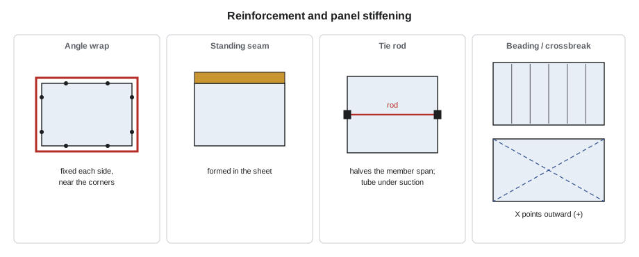
Reinforcement members
Several kinds of member are used, and a shop usually keeps a few sizes in stock.
- Steel angles are the traditional member. A galvanized angle is cut to length for each side, fixed to the duct with screws, rivets or welds at the spacing the standard requires, and joined at the corners, either tied to the next side's angle or simply butted. Angles are strong and easy to buy but slow to fit.
- Formed channels and zee sections are rolled from sheet on the shop's own machines, often as part of the coil line, and fixed the same way.
- Manufactured stiffeners are proprietary formed members designed to be fast to fit, with listed ratings.
- Standing seams and standing slips, formed in the sheet itself, add stiffness where they run across a side.
The member must be fixed to the duct closely enough to hold the sheet: the standard gives a maximum spacing for the screws or rivets, and the member must be fixed to each side near the corners. On positive-pressure duct the member resists the sheet pushing outward, so it is fixed on the outside, and the fasteners are in tension; on negative pressure the sheet pulls inward and the member, still usually outside, must be fixed firmly enough to pull the sheet back, which is why the standard's negative-pressure fastening rules are stricter.
Tie rods
On very wide ducts, a reinforcement member on its own would need to be impractically large to span the whole width. The standard allows tie rods instead: threaded steel rods or tubes running across the inside of the duct from one side to the opposite side, fixed to the reinforcement members with nuts and washers. A tie rod divides the span of the member in two, so a lighter member can be used. Under positive pressure the rod is in tension, holding the two sides together; under negative pressure it is in compression, and the standard limits its length or requires a tube or a larger rod.
Tie rods have costs as well as benefits. They are an obstruction inside the duct, they need sealing where they pass through the sheet in seal class A work, and they can whistle at high velocity if they are not streamlined. The standard sets where they are allowed. Some specifications forbid them in certain systems, such as kitchen exhaust or duct that must be cleaned. Keelson's practice was to use them only where the standard required them or where they saved a large member, and always to seal the penetrations.
A worked layout
The Ashgrove rooftop unit discharged into a plenum box 1200 by 600 mm, 1.5 m long, before the trunk began. From the chart, at 500 Pa and a 1200 mm larger side, it was 1.00 mm sheet with reinforcement every 0.9 m. Kai laid out its reinforcement with the script below, using Keelson's rule that sides wider than 1050 mm get a tie rod at each intermediate member.
# Reinforcement layout on a rectangular duct section (illustrative Keelson rules)
w, h, length = 1200, 600, 1500        # mm
spacing = 900              # reinforcement spacing from the chart, mm
joint = 1500                # joint spacing (section length), mm
tie_over = 1050            # sides wider than this get a tie rod at each reinforcement, mm
n = int(length // spacing) - 1 if length % spacing == 0 else int(length // spacing)
pos = [round(spacing * (k + 1), 3) for k in range(n) if spacing * (k + 1) < length]
print(f"section {w} x {h} mm, {length} mm long; joints at each end count as reinforcement")
print("intermediate reinforcement at", pos, "mm from the upstream joint")
ties = sum(1 for side in (w, h) if side > tie_over) * len(pos)
print(f"tie rods: {ties}  (one across each side wider than {tie_over} mm at each intermediate member)")
angle = '25 x 25 x 3 mm angle'
print(f"angle per member: 2 x ({w} + {h}) = {2 * (w + h)} mm of {angle}; total {2 * (w + h) * len(pos)} mm")section 1200 x 600 mm, 1500 mm long; joints at each end count as reinforcement intermediate reinforcement at [900] mm from the upstream joint tie rods: 1 (one across each side wider than 1050 mm at each intermediate member) angle per member: 2 x (1200 + 600) = 3600 mm of 25 x 25 x 3 mm angle; total 3600 mm
One intermediate member at 900 mm from the upstream joint was enough, because the joints at each end already reinforce the duct there and the remaining span to the downstream joint is only 600 mm. The 1200 mm sides were wider than 1050 mm, so the member needed one tie rod across them, and the whole wrap took 3.6 m of angle. Kai checked the joint rating at both ends of the section against the standard's requirement for the same spacing, and the formed flanges met it.
Walt checked it with one question: where is the largest unsupported span on each side? It was the 900 mm, or 36 in, span from the upstream joint to the member, which equalled the chart spacing. Had the member been placed in the middle of the section, both spans would have been 750 mm, or 30 in, which is also fine and slightly better; Kai moved it to the middle, because the shop's habit was to keep spans even when a section needed only one member.
Negative pressure
Return and exhaust duct under suction behaves differently. The sides pull inward, so the reinforcement must hold the sheet from being sucked in, and the corners and seams are loaded in a different way. Round duct, which needs no reinforcement under positive pressure, can collapse under suction if it is large and thin, and the standard gives reinforcement rings for large negative round duct. For rectangular negative duct, the tables are similar in form but stricter in detail: closer fastener spacing, a required attachment of the member to the sheet at every side, and limits on tie rods in compression.
The Ashgrove gym return was in the −250 Pa class, which is low enough that its gauge and joints handled it without intermediate reinforcement except on the largest pieces. The Eastgate hospital, by contrast, had a large exhaust system at −750 Pa, and Lin's estimate allowed for reinforcement every 0.6 m on the biggest risers. Those pieces would be built with tube tie rods instead of plain rods, because the rods would be in compression.
Worked problem
Number of intermediate members
A section is 1.5 m long and the table requires reinforcement every 0.6 m. How many intermediate members are needed, and where?
Show solution
- The joints at 0 and 1.5 m count as reinforcement.
- Spans must not exceed 0.6 m, so 1.5 ÷ 0.6 = 2.5, rounded up to 3 spans.
- Three spans need two intermediate members, at 0.5 m and 1.0 m for even spans.
Answer: Two members, at 0.5 m and 1.0 m from one end.
Reinforcement and fittings
Fittings need reinforcement too. An elbow, a transition or a plenum has sides as wide as the straight duct around it, often wider, and the standard requires them to be reinforced on the same basis, measured along the fitting's own length. The heel of a large radius elbow and the large end of a transition are typical places where reinforcement is forgotten. On a square elbow with turning vanes, the vane rails stiffen the diagonal, but the cheeks still need their own reinforcement if they are large. Casings and plenums, Lesson 9's subject, follow their own rules.
Walt's habit, when Kai brought him a fitting drawing, was to put his finger on each flat side and ask what held it. If the answer was a joint or a member within the spacing the table allowed, the side was fine. If the answer was nothing, the fitting needed another member.
Fixing and finishing
Good reinforcement is fixed firmly and neatly. The fasteners go through the member into the duct at the spacing the standard sets, close to each corner, and never so close to the edge of the sheet that they tear out. Screws and rivets through the duct wall are holes, and in seal class A work they are sealed, usually with a dab of sealant on each fastener or a sealing washer. Members are cut square and their ends tied or butted so the wrap is continuous around the duct. A member that rattles because its fasteners are loose or too few undoes its purpose; it becomes a source of noise instead of a cure for it.
On galvanized duct, the cut ends of angles and tie rods are touched up with zinc-rich paint where the specification asks for it, and on duct that will be insulated outside, the reinforcement is planned so the insulation can go over it without gaps.
Common mistakes
MistakeCounting only intermediate members as reinforcement.
InsteadTransverse joints reinforce the section ends and must have the rating the table requires.
MistakePlacing a single member off-centre without reason.
InsteadKeep spans even; the largest span must not exceed the table's spacing.
MistakeUsing plain rods as ties in negative duct.
InsteadRods in compression need tubes or larger sizes, as the standard requires.
MistakeForgetting to reinforce fittings.
InsteadFittings and plenums need reinforcement on the same basis as straight duct.
MistakeLeaving fastener holes unsealed in seal class A work.
InsteadSeal every penetration, including reinforcement screws and tie rods.
Summary and key terms
- Reinforcement divides each side into shorter spans so it does not bow under pressure.
- The standard's tables combine gauge, reinforcement spacing and member stiffness for each width and pressure class.
- Transverse joints are reinforcement at the section ends; intermediate members are added when the spacing is shorter than the section.
- Members include angles, formed channels, manufactured stiffeners and standing seams, fixed at the spacing the standard sets.
- Tie rods across wide ducts halve the member span; in negative duct they are in compression and need tubes.
- Fittings, plenums and casings need reinforcement too.
- Intermediate reinforcement
- A stiff member fixed around or across a duct between its transverse joints.
- Joint reinforcement
- The stiffness a transverse joint provides at the end of a section.
- Reinforcement spacing
- The largest allowed distance between reinforcing lines along a duct.
- Tie rod
- A rod or tube across the inside of a wide duct, fixed to reinforcement members on opposite sides.
- Span
- The unsupported length of a duct side between two reinforcing lines.
- Rating
- The stiffness class of a joint or member in the standard.
Practice problems
Work each problem on paper first, then reveal the answer to check.
A 1.2 m section needs reinforcement every 0.75 m. How many intermediate members?
Show answer
Spans of no more than 0.75 m: 1.2 ÷ 0.75 = 1.6, so 2 spans and 1 member, at 0.6 m.
Why do tie rods in negative duct need tubes?
Show answer
They are in compression and a thin rod would buckle.
What two things does a transverse joint do?
Show answer
It joins sections and reinforces the section ends.
Where should a single intermediate member go?
Show answer
Usually at mid-length, keeping both spans equal and within the table's spacing.
Lesson quiz · 5 questions
Score 60% or more to complete this lesson.
Create a free account to save your progress, take quizzes and earn a certificate.