
SMW-220 · Lesson 12 of 12 · 19 min
Capstone: the Ashgrove library supply trunk
By the end of his second-year rotation on the fabrication floor, Kai had made pieces of every kind the course has covered. Walt's last test for him was to take one complete run from shop drawing to loading dock on his own: the Ashgrove library supply trunk, from the plenum on the rooftop unit's discharge through the stepped-down rectangular trunk to the round branches that fed the library's diffusers. He would check the drawings against the specification, choose the construction for each piece from the standard, do the material take-off, build the pieces, check them, label them and stage them for Sean's crew. This capstone follows that job and ties the course together.
The run
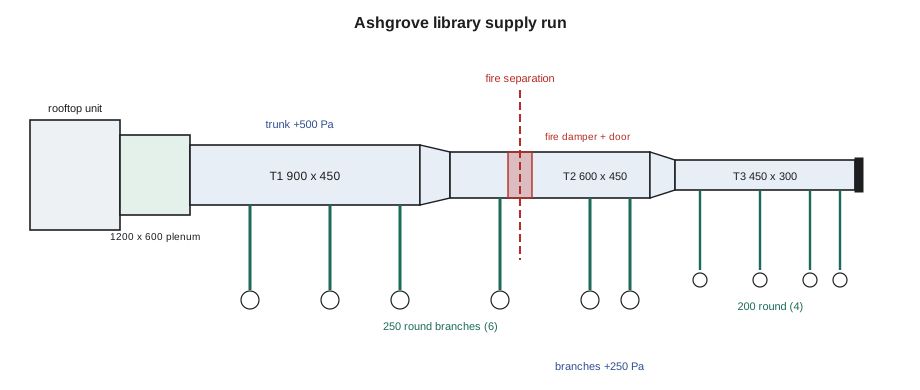
Lin's shop drawing showed the run in five parts. The plenum, 1200 by 600 mm and 1.2 m long, on the rooftop unit's discharge. Trunk T1, 900 by 450 mm, 7.5 m long in five sections, carrying the full flow. Trunk T2, 600 by 450 mm, 6.0 m in four sections, after the first branches. Trunk T3, 450 by 300 mm, 4.5 m in three sections, to the end. And ten round branches, six 250 mm round 3.0 m long and four 200 mm round 2.4 m long, each with a conical-entry spin-in and a damper. There were transitions between the trunk sizes, one vaned square elbow under a beam in T2, and access doors at the two fire dampers where the trunk crossed the library's fire separation.
Step 1: read the specification and the drawings
Kai began where Walt always began: with the ductwork section of the specification, pinned at his bench. It named the SMACNA HVAC Duct Construction Standards as the construction standard; set the supply trunk from the unit to the last branch at the 500 Pa positive class and the branches at the 250 Pa class; required seal class A throughout; required a leakage test on a share of the trunk, at a leakage class of 4; called for galvanized steel with a moderate coating, formed flanges or approved manufactured flanges on rectangular duct over a set size, and gasketed couplings on round; and required clean duct, capped at the shop and on site.
He then checked each piece on Lin's piece list against the mechanical drawing: sizes, pressure classes and the positions of branches, dampers and access doors. He found one question, the branch VD-3 from Lesson 8, already corrected to the larger size, and one new one: the access door at the second fire damper was drawn on the side of the trunk facing a wall. He marked it and asked Lin, who moved it to the other side to match the ceiling access panel.
Step 2: choose the construction
From the standard, as simplified in Keelson's chart, Kai chose the construction for each rectangular piece by its larger side and class: the plenum in the heaviest gauge with one intermediate member and a tie rod, as Lesson 4 laid out; T1 in the next gauge down with reinforcement within the chart's spacing; T2 and T3 lighter, with the formed-flange joints serving as the only reinforcement on their 1.5 m sections. All longitudinal seams would be Pittsburgh locks, sealed in the pocket. The transitions and the square elbow took the gauge of their larger ends, with the elbow's vanes on rails across its diagonal. Panels wider than the chart's limit would be beaded on the coil line.
The round branches were purchased spiral in the lightest gauge for their class, with gasketed couplings; the spin-in fittings with dampers came from the supplier, and the shop cut and framed their openings in the trunk sections. Every fastener through the trunk wall would be sealed, as seal class A requires, and the quadrants on the round dampers were standoff types, because the branches would be insulated.
Step 3: the take-off
The take-off gives the metal for the job, by gauge, so the shop can check that the right coils and sheet are on hand. Kai's script took the run piece by piece, assigned each rectangular piece its gauge from the chart, added the round branches, and summed the area and weight by gauge, with an allowance for scrap. It counts the duct walls only; the fittings, which come from sheet on the plasma table, were taken off separately by Lin's software.
# Ashgrove library supply trunk: full take-off by section
import math
chart = [(300, '0.55 mm'), (450, '0.70 mm'), (750, '0.70 mm'), (1050, '0.85 mm'), (1350, '1.00 mm'), (1800, '1.31 mm'), (2400, '1.31 mm')]
weight = {'0.55 mm': 4.6, '0.70 mm': 5.8, '0.85 mm': 7.0, '1.00 mm': 8.2, '1.31 mm': 10.6}
def gauge(w):
    return next(g for lim, g in chart if w <= lim)
runs = [('T1', 900, 450, 7500), ('T2', 600, 450, 6000), ('T3', 450, 300, 4500), ('plenum', 1200, 600, 1200)]               # (tag, width, height, length)
rounds = [('B250', 250, 3000, 6), ('B200', 200, 2400, 4)]           # (tag, diameter, length, count)
sheet = {}
for tag, w, h, length in runs:
    g = gauge(max(w, h)); a = 2 * (w + h) * length / 1e6
    sheet[g] = sheet.get(g, 0) + a
    print(f"{tag:<10} {w} x {h} x {length} mm  {g}  {a:.1f} m²")
for tag, d, length, n in rounds:
    g = '0.55 mm'; a = math.pi * d * length * n / 1e6
    sheet[g] = sheet.get(g, 0) + a
    print(f"{tag:<10} {d} round x {length} mm x {n}  {g}  {a:.1f} m²")
tot_a = sum(sheet.values()); tot_w = sum(a * weight[g] for g, a in sheet.items())
for g, a in sorted(sheet.items()):
    print(f"  {g}: {a:.1f} m², {a * weight[g]:.0f} kg")
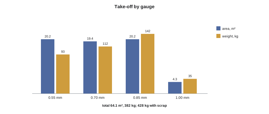
print(f"total {tot_a:.1f} m², {tot_w:.0f} kg before scrap; with 12 percent scrap {tot_w * 1.12:.0f} kg")T1 900 x 450 x 7500 mm 0.85 mm 20.2 m² T2 600 x 450 x 6000 mm 0.70 mm 12.6 m² T3 450 x 300 x 4500 mm 0.70 mm 6.8 m² plenum 1200 x 600 x 1200 mm 1.00 mm 4.3 m² B250 250 round x 3000 mm x 6 0.55 mm 14.1 m² B200 200 round x 2400 mm x 4 0.55 mm 6.0 m² 0.55 mm: 20.2 m², 93 kg 0.70 mm: 19.4 m², 112 kg 0.85 mm: 20.2 m², 142 kg 1.00 mm: 4.3 m², 35 kg total 64.1 m², 382 kg before scrap; with 12 percent scrap 428 kg
The straight duct and plenum came to about 64 m² of sheet and about 380 kg, rising to about 430 kg with 12 percent allowed for scrap, seams and joints. The lightest gauge, for the round branches, and the 0.70 mm for T2 and T3 made up most of the area; the heavier gauges were a smaller area but a larger share of the weight. Walt checked the 0.85 mm figure against the coil on the line, which had enough for T1 with a margin, and ordered a small extra stock of 1.00 mm sheet for the plenum.
Step 4: cut lists and fabrication
Kai prepared the cut lists. For the coil line, he grouped the straight sections by gauge: T1 first, made in four pieces because its L blank was wider than the coil, as Lesson 11 found; then T2 and T3 as two-piece Ls. For the plasma table, Lin's software nested the transitions, the square elbow's cheeks and the plenum's panels. He checked the first piece of each coil-line run and the first transition off the table against the drawings before the rest were made.
Then he built. The plenum came first, laid out flat, squared on its diagonals at each stage, with its intermediate member and tie rod fixed and sealed, and its unit connection flange checked against the rooftop unit's submittal dimensions. The trunk sections followed off the coil line, folded, seamed with sealant in each Pittsburgh pocket and closed. The square elbow got its vane rails and vanes before its second cheek was fixed. The trunk sections with branches had their spin-in openings cut and framed while they could still lie flat. The two sections with fire damper access doors had their door frames cut in on the corrected side.
Throughout, Kai followed the habits the course built: gauges from the larger side, reinforcement checked at each flat side, seams closed along their full length, every penetration sealed, liner none on this run, vanes counted from the rail pattern, and nothing built that he thought was wrong without asking.
Step 5: check, label and stage
Every piece got the Lesson 11 checks: inside size at each end, diagonals, length, gauge, seams, reinforcement, vanes, openings and doors. Two pieces failed. One T2 section was 3 mm, or 1/8 in, out of square on its diagonals, from a Pittsburgh lock closed unevenly; Kai reopened and reclosed it. One transition had a dent from being set down on a bolt head; it was small enough to be worked out without damaging the coating, which Walt approved. Both were noted on the job's quality sheet.
Each piece was labelled with the job, piece number, size, gauge, class, seal class, system and floor, with a flow arrow, and capped at both ends with film. Sean wanted the plenum and T1 first, because the rooftop unit was being set that week, so the truck was loaded with the branches and T3 at the front, T2 behind them and the plenum and T1 at the back, to come off first. The boxes of couplings, sealant, hangers and spin-ins for each delivery were labelled with the delivery number, and the delivery ticket listed every piece.
Worked problem
Checking the trunk velocities against the class
Is the 500 Pa class still right if the designer raises the library flow by 10 percent, so the trunk's highest static pressure rises from about 430 Pa to about 520 Pa?
Show solution
- 520 Pa is above 500 Pa, the top of the class.
- The next class up is 750 Pa.
Answer: No: the trunk would move to the 750 Pa class, which can change gauges, joints and reinforcement, so the shop must stop and ask before building.
Step 6: the field and the test
Sean's crew hung the run over two days, joined the formed flanges with their corner pieces, cleats and gaskets, sealed the flange corners and the round couplings, and snapped in the spin-ins. The engineer's leakage test on two sections of T1 and the plenum, at the specification's test pressure, came in well under the allowed leakage for class 4. SMW-310 covers the field work and the test in detail. The balancer, at the end of the job, found the library diffusers within their design flows after only small damper adjustments, which is the best sign that a run was built as drawn.
Walt's review of Kai's capstone was short. The take-off matched the metal used within a few percent. The two failed pieces had been caught in the shop. The access door question had been caught before cutting. The truck had been loaded in the order the crew needed. That, he said, was what a duct fabricator does.
What the course has covered
This course has taken the pattern and joining skills of the first year and turned them into finished duct built to a standard. It covered the parts of a duct system and the quantities that describe it; the construction standard and its pressure, seal and leakage classes; rectangular duct gauges, seams and joints; reinforcement and tie rods; round and spiral duct; flat oval, double-wall and lined duct and the fire rules for their materials; elbows, vanes, takeoffs and transitions; volume and backdraft dampers; access doors, plenums and casings; special materials for corrosive exhaust; and the shop's workflow and quality checks. SMW-230 adds thin-gauge welding, SMW-310 the field installation and testing, and SMW-410 and SMW-420 the industrial systems and the shop's drawings and machines.
Lessons Kai wrote down
At the end of the capstone, Walt asked Kai to write down what he would do differently next time. Kai's list had three items. He would check access sides against the reflected ceiling plan, not only against the mechanical drawing, before Lin issued the piece list. He would run the coil-width check on every section size before the cut list went to the coil line, not after. And he would mark the delivery order on the cut list itself, so the shop could build in the order the truck would be loaded and not have to sort finished pieces at the dock. Walt added the third item to the shop's standard practice.
Common mistakes
MistakeStarting fabrication before reading the specification.
InsteadRead the ductwork section first and keep it at the bench.
MistakeTaking the shop drawing's access side on trust.
InsteadCheck door and quadrant sides against the ceiling access.
MistakeIgnoring a design change that moves a section into a higher class.
InsteadStop and ask; the construction may change.
MistakeLeaving out-of-square pieces for the field to force.
InsteadFix them on the bench and record the cause.
MistakeLoading the truck in the order of fabrication.
InsteadLoad in reverse order of installation, with small parts boxed by delivery.
Summary and key terms
- The capstone took one run from shop drawing to delivery: specification, construction, take-off, fabrication, checks and staging.
- Construction was chosen from the standard by size, pressure class and seal class for every piece.
- The take-off summed sheet by gauge, with an allowance for scrap, and was checked against stock.
- First-piece checks and final checks caught errors in the shop, where they are cheapest to fix.
- Labels, caps and delivery staging let the field crew install quickly and trust the pieces.
- A leakage test and a smooth balance are the evidence that a run was built well.
- Take-off
- A count of material by gauge and type for a run or job.
- Run
- A continuous path of duct from a source to its outlets.
- Quality sheet
- A record of checks, failures and corrections for a job.
- Delivery ticket
- A list of every piece and part in one delivery.
- Fire separation
- A fire-rated wall or floor that duct crosses through a fire damper.
- End cap
- A sealed closure at the end of a trunk.
Practice problems
Work each problem on paper first, then reveal the answer to check.
Why was T1 made from four pieces?
Show answer
Its two-piece L blank was wider than the coil.
What was the take-off's total weight with scrap?
Show answer
About 430 kg.
What should the shop do if a design change raises a section's pressure above its class?
Show answer
Stop and ask; the next class can change the construction.
Why were the plenum and T1 loaded last onto the truck?
Show answer
So they came off first, because they would be installed first.
Lesson quiz · 5 questions
Score 60% or more to complete this lesson.
Create a free account to save your progress, take quizzes and earn a certificate.