
SMW-120 · Lesson 3 of 12 · 13 min
The principle of parallel line development
Every parallel line pattern, from a simple cut prism to a five-piece elbow, follows the same small set of steps. Learn the steps once and the rest of this course is practice in applying them to different shapes. This lesson sets out the principle behind the method, the vocabulary pattern makers use for it, and the standard sequence Kai would follow for every pattern in the course, using a small hexagonal prism cut on a slope as the first example.
Why the method works
Imagine a straight pipe or a prism with lines drawn along its surface, all parallel to its axis. These are element lines. Now imagine slitting the surface along one element line and unrolling it onto a flat sheet. Every element line lands on the sheet as a straight line, still parallel to the others, still at its true length. The distance between neighbouring element lines on the sheet is the distance between them measured around the surface of the object. And the edge of the unrolled surface, the line through the ends of all the element lines, is the shape the cut takes when the surface is laid flat.
That is the whole idea. The pattern is a set of parallel lines, spaced by the girth of the object and cut to the lengths the object needs. The plan view gives the spacing around the girth. The elevation gives the lengths. A pattern maker transfers one to the other, joins the ends and adds the allowances for seams.
Parallel line development works only for surfaces whose element lines are parallel: prisms, cylinders and anything built from pieces of them, such as elbows, tees, offsets, copings, gutters, mitred flashings and the straight sides of roof jacks. A cone, whose lines all meet at the apex, cannot be developed this way, because its lines are not parallel. That is radial line development, in SMW-210.
The vocabulary
Pattern makers use a handful of words for the parts of a parallel line layout, and the shop uses them all the time, so it is worth learning them precisely.
- The stretchout line is a straight line on the pattern, square to the element lines, whose length is the girth of the object: the perimeter of a prism or the circumference of a pipe. It is usually drawn as an extension of the base line of the elevation, so that heights can be projected straight across.
- Element lines, sometimes called measuring lines, are the parallel lines on the object and on the pattern. On a prism they are usually the corners; on a pipe they are drawn at the equal divisions of the plan.
- The base line is the line on the elevation from which all heights are measured. It must be square to the element lines, and on the pattern it becomes the stretchout line.
- The cut line, mitre line or line of intersection is the line where the object is cut or meets another object. Its shape on the pattern is what the method finds.
- The seam line is the element line along which the pattern is opened, which becomes the longitudinal seam of the finished part. Choosing where to put it is a design decision, not an accident.
Points are numbered in the plan and carried to the elevation and then to the pattern with the same numbers, so that every height ends up on the right element line. The seam line usually takes the number 1 at both ends of the stretchout.
The standard sequence
Aggie gave Kai the sequence written on a card, and he kept it pinned above the layout bench for the rest of the year.
- 1. Draw the elevation full size, with a base line square to the element lines.
- 2. Draw the plan, or a half plan for a symmetrical object, lined up with the elevation.
- 3. Divide the plan into spaces: at every corner for a prism, into 12 or more equal parts for a pipe. Number the points, starting at the seam.
- 4. Project each point from the plan into the elevation as an element line, and mark where it meets the cut line.
- 5. Draw the stretchout line as an extension of the base line, and set off along it the spaces from the plan in the same order, numbering each.
- 6. Draw element lines square to the stretchout through each point.
- 7. Project the heights from the elevation across to the matching element lines, or measure them up from the base line, and mark each point.
- 8. Join the points with straight lines for a prism or a smooth curve for a pipe, add the seam and edge allowances, and check.
The sequence never changes. What changes from one fitting to the next is the shape of the plan, the shape of the cut line and the allowances.
The first example: a cut hexagonal prism
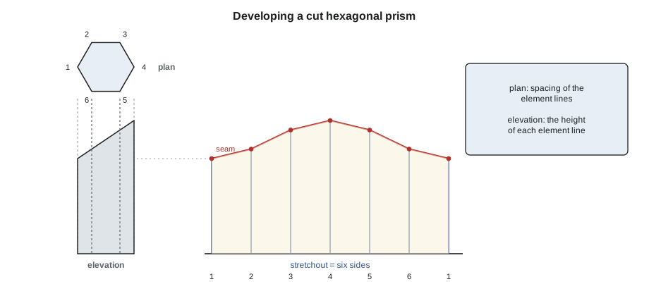
The first pattern Kai developed was a teaching piece Aggie used with every apprentice: a hexagonal prism with sides of 60 mm, 150 mm tall at its shortest corner, with its top cut on a slope so that the corner opposite the shortest one is 210 mm tall. The pattern is the six faces unrolled side by side.
In the plan, the hexagon's six corners became the six element lines, numbered 1 to 6 from the shortest corner. The slope of the cut ran across the hexagon from corner 1 to corner 4, so corners 2 and 6 were at the same height, as were corners 3 and 5. In the elevation, Kai drew the slope and projected each corner up to it to find its height. Then he drew the stretchout line, six side lengths long, numbered the spaces 1, 2, 3, 4, 5, 6 and back to 1, erected element lines and carried the heights across.
Because the faces of a prism are flat, the top edge of the pattern between two element lines is a straight line. Kai joined the points with a straightedge. The pattern was a strip with a zigzag top, high in the middle at corner 4 and low at both ends where corner 1 would form the seam.
The script calculates the height of each corner of a regular prism cut by a sloping plane. Each corner's height depends on its distance across the plan in the direction of the slope, so it is the shortest height plus the slope times that distance.
# Heights of the corners of a regular prism cut by a sloping plane
import math
sides, side = 6, 60     # sides, mm per side
h_low, h_high = 150, 210  # mm         # at corner 1 and at the opposite corner
r = side / (2 * math.sin(math.pi / sides))     # circle through the corners
across = 2 * r                                 # corner 1 to the opposite corner, in plan
slope = (h_high - h_low) / across
print(f"stretchout = {sides} x {side} = {sides * side} mm")
for k in range(sides):
    ang = 2 * math.pi * k / sides              # corner 1 at angle 0
    dist = r - r * math.cos(ang)               # distance from corner 1, along the slope
print(f"corner {k + 1}: at {k * side:>4} mm along the stretchout, height {h_low + slope * dist:.1f} mm")stretchout = 6 x 60 = 360 mm corner 1: at 0 mm along the stretchout, height 150.0 mm corner 2: at 60 mm along the stretchout, height 165.0 mm corner 3: at 120 mm along the stretchout, height 195.0 mm corner 4: at 180 mm along the stretchout, height 210.0 mm corner 5: at 240 mm along the stretchout, height 195.0 mm corner 6: at 300 mm along the stretchout, height 165.0 mm
The output matched Kai's drawing: 150, 165, 195, 210, 195 and 165 mm at the six corners. He cut the pattern from 0.55 mm galvanized scrap, bent it on the corners in the box and pan brake, and closed it with a lap seam. The top edge lay in one flat plane, which was the test of a correct pattern: a sheet of cardboard laid on top of the finished prism touched it all the way round.
Projecting or measuring
There are two ways to carry heights from the elevation to the pattern. Projecting means extending a line from each point on the elevation straight across, parallel to the stretchout, until it meets the matching element line. Measuring means taking each height with dividers or a rule from the base line of the elevation and setting it off up the element line from the stretchout. Projecting is faster and less error-prone when the pattern is drawn beside the elevation on the same sheet. Measuring is necessary when the pattern is on a different sheet, or when the elevation was drawn on layout paper and the pattern goes straight onto metal.
Either way, every height is measured from the same base line. The most common error in a first pattern is to measure some heights from the base and others from the top of the elevation, or from a line that is not square to the elements. The result is a pattern that looks plausible and is wrong.
Where to put the seam
The seam line is chosen before the plan is numbered, because it fixes where the stretchout starts. Several things decide it. The seam should usually be on the shortest element line, so the seam is short, easy to close and uses the least material for the seam allowance. On a fitting that will be seen, the seam goes where it will be least visible, often at the back or underneath. On an elbow or tee, the seam is placed so that it does not fall where two pieces join, because closing a seam through a joint is difficult. And on prisms, the seam is placed at a corner, where it can be formed as a corner lock, rather than in the middle of a flat face.
For the hexagonal prism, the seam was at corner 1, the shortest. For the cut pipes of Lesson 5, it will be at the short side of the cut. For elbows in Lessons 6 and 7, it alternates between the throat and the heel of neighbouring pieces, which saves material and keeps seams from lining up.
Allowances, briefly
A pattern drawn by the sequence above is the net shape of the metal: the exact outline of the finished surface. Before it is cut, allowances are added: extra metal along the seam line for the longitudinal seam, and extra along the cut edge and the base for whatever joint the part makes with its neighbours. Lesson 11 covers the allowances used in this course, and SMW-130 covers seams and joints in full. For now, the rule is to draw the net pattern first, then add the allowances outside it as separate lines, so the net shape is never lost.
Checking a pattern
A pattern is checked before it is cut. Four checks catch most errors. The stretchout must equal the girth: the sum of the sides of a prism or the circumference of a pipe at its mean diameter. The element lines must be square to the stretchout. Element lines that are the same height on the object, such as corners 2 and 6 of the hexagon, must be the same height on the pattern, which checks the symmetry. And the two ends of the pattern, which will join at the seam, must be the same height, because they are the same element line.
Aggie added a fifth check for every first pattern: make it in cheap material or card, form it, and look at it. A pattern that is right looks right. A pattern with one height wrong has a visible kink in its edge.
Parallel line work beyond duct
The same sequence develops many non-duct shapes. A rectangular downspout with a sloped outlet, a square roof jack cut to a pitch, a gutter end cap, a sloped sill flashing and a triangular cricket face are all prisms or parts of prisms. Architectural sheet metal workers develop these daily, often from a sketch made on the roof, and the habit of numbering points and measuring from a single base line is as useful on a roof as it is on the layout bench.
A useful exercise is to develop the same object twice, once by projecting heights across from the elevation and once by measuring each height with a rule, and to compare the two patterns. They should be identical. If they are not, one method has a mistake that the other has not, and finding it teaches more than either pattern alone.
Common mistakes
MistakeMeasuring some heights from the base line and others from the top.
InsteadMeasure every height from one base line square to the elements.
MistakeNumbering the pattern in a different order from the plan.
InsteadNumber the plan from the seam and carry the same numbers to the pattern.
MistakeJoining the points of a pipe pattern with straight lines.
InsteadUse straight lines between the corners of a prism, but a smooth curve for a pipe.
MistakePutting the seam on the longest side.
InsteadPut it on the shortest element where possible, away from joints and visible faces.
MistakeDrawing the allowances first and the net pattern inside them.
InsteadDraw the net pattern, then add allowances outside it.
Summary and key terms
- Parallel line development unrolls a surface made of parallel element lines.
- The plan gives the spacing along the stretchout; the elevation gives the true lengths.
- The standard sequence is elevation, plan, divide and number, project, stretchout, element lines, heights, join and check.
- Every height is measured from one base line square to the elements.
- The seam usually goes on the shortest element line, away from joints and visible faces.
- Draw the net pattern first, then add allowances; check the stretchout, squareness, symmetry and seam ends.
- Element line
- One of the parallel lines on the surface of a prism or pipe, at true length in the elevation.
- Stretchout line
- The line on a pattern equal in length to the girth of the object.
- Base line
- The line square to the elements from which every height is measured.
- Seam line
- The element line along which a pattern is opened and later closed by a seam.
- Girth
- The distance around an object: the perimeter of a prism or circumference of a pipe.
- Net pattern
- The exact outline of the finished surface, before allowances are added.
Lesson quiz · 5 questions
Score 60% or more to complete this lesson.
Create a free account to save your progress, take quizzes and earn a certificate.