
RAC-430 · Lesson 5 of 12 · 17 min
Electrical and control faults
Electrical and controls was where Theo's diagnostic score had been weakest, and he knew why. Four years of meters had made him quick in the field, but he did the arithmetic in his head or on the meter, not on paper, and he had forgotten some of the rules behind it. On the Red Seal exam, electrical and control questions are spread across several blocks: routine trade activities, installation, commissioning and above all maintenance and service. This lesson reviews the electrical side of troubleshooting as a sequence of checks, from power supply to motor windings, with the calculations the exam expects.
Every check in this lesson is done with the safety practices from RAC-130 in place: the right meter with the right category rating, the right protective equipment for the task, voltage tests on live circuits done only when necessary and by a qualified person, and lockout before any work on conductors or components. Exam questions test those practices as often as they test the electrical theory.
A sequence for electrical faults
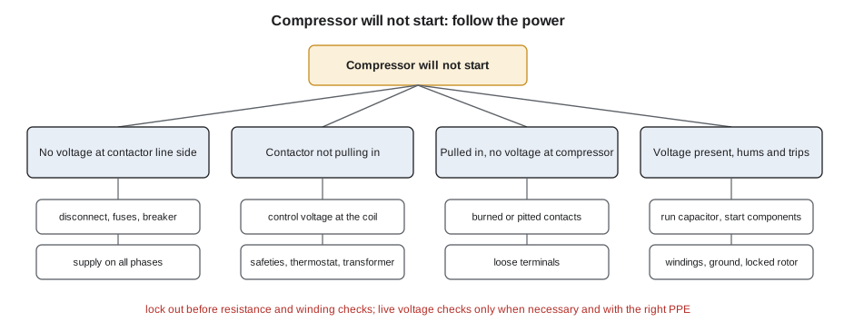
Electrical problems follow the power. The sequence Dana taught was to start at the supply and move toward the load, checking at each point that what should be there is there.
First, the supply. Is the voltage at the unit's disconnect within the equipment's range, usually within about 10 % of the nameplate voltage? On three-phase equipment, are all three phases present and balanced? Voltage unbalance of more than a couple of percent causes current unbalance several times larger and overheats motors, as the seniors' residence pump in RAC-130 showed. A missing phase, single-phasing, stops three-phase motors from starting and burns them out if they keep trying, as the make-up air unit with the loose fuse clip did.
Second, the control circuit. Is the transformer delivering its rated secondary voltage under load? Is the thermostat or controller calling? Are the safety controls closed: high-pressure and low-pressure switches, overloads, freeze stats, door switches? A control circuit is a series of switches; a voltmeter across each one, with the circuit energized and calling, shows which one is open, because the open switch has the full control voltage across it. The clinic rooftop unit's overloaded 40 VA transformer in RAC-130 dropped to under 19 V when its economizer actuator was added, and the contactor chattered.
Third, the switching devices. Is the contactor coil getting its voltage? Is the contactor closing? Are its contacts in good condition? A pitted contact has a voltage drop across it when closed and carrying current; a few volts across a closed pole means it is burning and must be replaced, as the clinic contactor's 2.6 V drop showed.
Fourth, the load. Is the motor or compressor getting full voltage at its terminals when it tries to start? What current does it draw, compared with rated load amps and locked-rotor amps? Is the run capacitor within tolerance? Are the windings continuous and insulated from ground?
Motors, capacitors and windings
Single-phase compressors and fan motors are the most common electrical faults on residential and light commercial calls, and the most common exam topic in the electrical area. A permanent split capacitor motor has a run winding and a start winding with a run capacitor in series with the start winding. A capacitor-start capacitor-run compressor adds a start capacitor and a start relay or a hard-start kit. Each part fails in its own way, and each failure has a recognizable signature.
A weak or failed run capacitor reduces the start winding current, so the motor runs hotter and draws more current on the run winding, and may not start at all under load. It can be checked with a capacitance meter with the capacitor discharged and disconnected, or under load with the formula for 60 Hz systems: microfarads equal 2,652 times the start winding current divided by the voltage across the capacitor. Most run capacitors are rated within about ±6 %, so a reading well outside that means replacement. The brewery condensing unit in RAC-130 had a 35 µF capacitor reading about 28 µF.
Winding faults are found with an ohmmeter, with the power off and locked out. On a single-phase compressor, the resistance from common to start is higher than common to run, and the two add up to the resistance from start to run. If they do not add up, a winding is open or shorted. A reading of zero ohms between two terminals means a short. An infinite reading means an open winding, or an open internal overload that will close when the compressor cools; a hot compressor with an open circuit between common and both other terminals should be left to cool, sometimes for hours, before it is condemned.
Insulation to ground is checked with a megohmmeter. A compressor that reads more than about 100 megohms is generally in good condition; one reading a few megohms is deteriorating; one with a near-zero reading is grounded and must not be restarted. Low readings on a hermetic compressor can come from liquid refrigerant in the shell, so a reading after the crankcase heater has run, or a trend over time, is more useful than a single number. The arena ice machine compressor in RAC-130 was grounded, and the severe burnout cleanup in RAC-210 followed.
The script applies those checks to readings of the kind the exam gives.
# Run capacitor and winding checks from field readings
def capacitor(start_winding_amps, volts_across_cap, rated_uf):
    uf = 2652 * start_winding_amps / volts_across_cap   # 60 Hz running estimate
    dev = (uf - rated_uf) / rated_uf
    ok = abs(dev) <= 0.06
    print(f"capacitor: {uf:.1f} uF measured against {rated_uf} uF rated ({dev:+.0%}) -> {'within tolerance' if ok else 'replace'}")

def windings(c_r, c_s, s_r):
    print(f"windings: C-R {c_r} ohm, C-S {c_s} ohm, S-R {s_r} ohm, C-R + C-S = {c_r + c_s:.1f}")
    if min(c_r, c_s, s_r) == 0: print("   a zero reading means a shorted winding")
    elif abs(c_r + c_s - s_r) > 0.3: print("   readings do not add up: suspect an open or shorted winding")
    else: print("   readings add up: windings are continuous; start is the higher of C-R and C-S")

def ground(megohms):
    verdict = "good" if megohms >= 100 else ("watch the trend" if megohms >= 20 else "do not restart; investigate")
    print(f"insulation to ground: {megohms} megohms -> {verdict}")

capacitor(4.1, 389, 35)     # the brewery condensing unit from RAC-130
capacitor(2.9, 398, 30)
windings(1.1, 2.8, 3.9)
windings(1.2, 0.0, 1.3)
ground(450); ground(35); ground(0.4)capacitor: 28.0 uF measured against 35 uF rated (-20%) -> replace capacitor: 19.3 uF measured against 30 uF rated (-36%) -> replace windings: C-R 1.1 ohm, C-S 2.8 ohm, S-R 3.9 ohm, C-R + C-S = 3.9 readings add up: windings are continuous; start is the higher of C-R and C-S windings: C-R 1.2 ohm, C-S 0.0 ohm, S-R 1.3 ohm, C-R + C-S = 1.2 a zero reading means a shorted winding insulation to ground: 450 megohms -> good insulation to ground: 35 megohms -> watch the trend insulation to ground: 0.4 megohms -> do not restart; investigate
The first capacitor reads 28 µF against 35, 20 % low: replace it. The second is even further out. The first set of winding readings adds up correctly: common to run 1.1 Ω, common to start 2.8 Ω, start to run 3.9 Ω. The second set has a zero reading from common to start: a shorted winding, and the compressor must be replaced. The megohm readings run from good, to a value worth watching on future visits, to a grounded compressor.
Three-phase motors and drives
Three-phase motors have no start winding or capacitor. They fail mostly from supply problems: unbalance, single-phasing, low voltage, and from overload and bearing failure. Their windings are checked by comparing the three phase-to-phase resistances, which should be nearly equal, and by megohm testing. Reversing two of the three supply phases reverses rotation, which matters for scroll compressors, whose bearings and seals suffer if they run backward, and for fans and pumps. The clinic's scroll compressor in RAC-210 ran backward after the utility rolled the phases, noisy and with almost no pressure difference, until two leads were swapped at the disconnect.
Variable-frequency drives and electronically commutated motors add electronics to the motor circuit. A drive reports faults by code: overcurrent, overvoltage on the DC bus, undervoltage, overtemperature, ground fault, loss of a phase. The first step with a drive fault is to read and record the code, then check the supply and the load, not to reset it repeatedly. Drives also produce harmonics and high-frequency voltage on motor leads, and some meters read them wrongly; a true RMS meter with a low-pass filter setting gives better readings on drive outputs. Electronically commutated fan motors have their own control signals, often a 24 V or PWM signal, and the manufacturer's diagnostic procedure is the right approach.
Boards, sensors and communicating systems
Modern equipment has control boards that run the sequence, monitor sensors and report faults. Boards fail less often than technicians think: a board is often replaced when the real fault is a sensor, a connection or the supply. The method is the same as for any control circuit: read the fault code and the board's diagnostic lights, check the inputs the board needs, check the outputs it is supposed to give and replace the board only when it has the right inputs and does not give the right outputs.
Thermistors and other sensors are checked against their resistance-temperature tables, with a reference thermometer at the sensor. A sensor reading several degrees off, or a corroded connector adding resistance, can make a system short-cycle, freeze or refuse to defrost, as the Lindqvist heat pump's slipped outdoor coil sensor did in RAC-230.
Communicating systems, such as the Bauer house's variable-speed heat pump and furnace in RAC-320, send data between indoor unit, outdoor unit and thermostat on a two- or four-wire bus. Faults show as communication errors on the thermostat or board. The checks are the bus wiring, the polarity, the termination and the supply to each device, then the manufacturer's diagnostic tool. Mixing conventional and communicating wiring, or using the wrong terminals, causes faults that look like failed boards.
| Symptom | Likely electrical causes | Confirming check |
|---|---|---|
| Compressor hums, trips on overload | Weak run capacitor, failed start components, low voltage, locked rotor | Capacitor test, voltage at terminals during start, amps |
| Contactor chatters | Low control voltage, overloaded transformer, poor connection | Control voltage under load at the coil |
| Three-phase motor will not start, hums | Single-phasing, blown fuse, loose connection | Voltage on all three phases at the motor |
| Repeated breaker trips | Grounded winding, short circuit, undersized breaker | Megohm test, resistance checks, nameplate MOCP |
| Fan runs slowly or stops when warm | Failed capacitor, worn bearings, overheating motor | Capacitance, spin test, amps |
| Board shows a sensor fault | Sensor out of range, loose or corroded connector | Sensor resistance against its table |
Two worked questions
Dana's practice questions for this lesson always included a safety step, because the exam's do. One read: "A condensing unit's contactor is pulled in, but the compressor does not run. There is 240 V on the line side of the contactor and 0 V on the load side. What is the problem?" The answer is a contactor whose contacts are not closing or are burned open, since voltage reaches the contactor but does not pass through it. A distractor offered a failed compressor winding, which would show voltage on the load side with no current.
Another read: "Before measuring the winding resistance of a single-phase compressor, what must the technician do first?" The options included measuring the run capacitor, checking the amperage and removing the terminal cover. The key was to disconnect and lock out the power and verify there is no voltage, then discharge the capacitor. Only after that is any resistance check safe, and only then are the readings meaningful, because an energized or charged circuit gives false readings and can injure the technician.
Common mistakes
MistakeMeasuring winding resistance without locking out the power.
InsteadLock out, verify zero energy and discharge capacitors before resistance checks.
MistakeCondemning a hot compressor with an open circuit between common and both windings.
InsteadAn internal overload may be open; let it cool and test again.
MistakeResetting a drive fault repeatedly without reading the code.
InsteadRecord the code and check the supply and load first.
MistakeReplacing a control board because it shows a fault code.
InsteadCheck the inputs and outputs; the fault is usually a sensor, connection or supply.
MistakeSwapping supply leads at random to fix rotation on a compressor.
InsteadVerify phase rotation with a meter and follow the manufacturer's procedure.
Summary and key terms
- Follow the power: supply, control circuit, switching devices, load.
- Across a series control circuit, the open switch has the full control voltage across it.
- Run capacitance at 60 Hz is about 2,652 times start winding current divided by capacitor voltage; most are rated within about ±6 %.
- On single-phase compressors, common-to-run plus common-to-start equals start-to-run; zero means a short, infinite an open winding or overload.
- Megohm readings above about 100 MΩ are generally good; trends matter more than single readings.
- Read drive and board fault codes and check inputs and outputs before replacing electronics.
- Single-phasing
- Loss of one phase of a three-phase supply, which stops three-phase motors from starting and overheats them.
- Run capacitor
- A capacitor in series with the start winding of a PSC motor that remains in circuit while it runs.
- Megohmmeter
- An instrument that tests insulation resistance at high voltage.
- Rated load amps
- The compressor current used to size circuit components, given on the nameplate.
- Communicating system
- Equipment whose thermostat and units exchange data over a bus rather than simple on/off signals.
Practice problems
Work each problem on paper first, then reveal the answer to check.
A capacitor's start winding carries 4.6 A with 380 V across it. What is its capacitance?
Show answer
2,652 × 4.6 ÷ 380 = about 32 µF.
C-R 1.4 Ω, C-S 3.1 Ω, S-R 4.5 Ω. Are the windings sound?
Show answer
Yes: 1.4 + 3.1 = 4.5.
A control circuit is calling but the contactor is not pulled in. The high-pressure switch has 24 V across it. What does that mean?
Show answer
The high-pressure switch is open.
A compressor reads 3 MΩ to ground today, 40 MΩ last year and 200 MΩ the year before. What should be done?
Show answer
Plan for replacement and check for causes such as moisture or acid; the trend is falling fast.
Lesson quiz · 5 questions
Score 60% or more to complete this lesson.
Create a free account to save your progress, take quizzes and earn a certificate.