
PWR-510 · Lesson 2 of 12 · 28 min
Design calculations for pressure equipment
▶ Video coming soon A video version of this lesson is on the way.
Ingeborg Haverlund, Keswold's reliability engineer, joined the second session with a folder of drawings. Keswold's heat recovery steam generator had been designed and built by a specialist manufacturer, and its pressure parts were designed to the ASME code by the maker's engineers. "So why does a chief engineer need to do design calculations?" Anselm asked. Morwenna answered with three questions of her own. "When a corroded section has to be assessed, who decides whether it can stay in service? When a contractor offers a repair, who checks that it restores the design? When a vendor quotes a new vessel, who checks that the design conditions on the drawing are the ones the plant needs?"
A chief engineer does not replace the designer, the manufacturer's engineers or the inspector, and only the code's own rules and the registered design govern a real vessel. But the chief must understand what those rules do, be able to check that numbers are sensible, and know when a question has to go to a qualified engineer. The First Class examinations ask candidates to work the code calculations with the code's formulas and references. This lesson explains the principles behind them with simple teaching relations that show how pressure, size, material and temperature drive the thickness and life of pressure equipment.
The code governs
In Ontario, CSA B51 and the TSSA code adoption document adopt the ASME Boiler and Pressure Vessel Code for design and construction, and a boiler, pressure vessel or fitting must have its design registered, with a Canadian registration number (CRN), before it is built or installed (PWR-340). The designer works to the code edition in force, with its formulas, allowable stress tables, joint efficiencies and rules for heads, openings, external pressure and supports. Nothing in this lesson replaces those formulas, and any real calculation must be done to the code and registered as the code adoption document requires.
The code relations for shells and heads are refinements of a few basic results from mechanics, adjusted for thick walls, joint quality, manufacturing tolerances and decades of experience. The basic results are worth knowing because they show which way the answer moves: double the diameter and the thickness doubles; double the allowable stress and the thickness halves; add corrosion and the thickness grows by the corrosion allowance.
Design conditions
Every pressure part starts with its design conditions: the design pressure, the design temperature, the corrosion allowance, and the other loads it must carry. The design pressure is set above the highest pressure expected in operation, with a margin so that the pressure relief devices can be set at or below the maximum allowable working pressure (MAWP) without the plant operating too close to their set pressure. The design temperature is the metal temperature the part will reach in service, which sets the allowable stress from the code's tables. The corrosion allowance is extra thickness added to cover expected metal loss over the design life.
- Pressure loads: internal pressure, external pressure or vacuum, and the static head of liquid in tall vessels and drums.
- Mechanical loads: weight of the vessel and contents, piping forces and moments on nozzles, wind and seismic loads, support reactions.
- Thermal loads: temperature differences through the wall and between parts during startup, shutdown and load changes.
- Cyclic loads: repeated pressure and temperature cycles that can cause fatigue over the life of the plant.
Keswold's high pressure drum operates at about 6,200 kPa absolute (900 psia) (PWR-320). For the teaching examples in this lesson, take the drum's design pressure as 7,000 kPa gauge (1,000 psig), its inside diameter as 1,500 mm (60 in), its material as SA-516 Grade 70 plate with a typical allowable stress of 138 MPa (20,000 psi) at its design temperature, fully radiographed seams so that the joint efficiency is 1.0, and a corrosion allowance of 3 mm (1/8 in). These are sample values for teaching; the real drum's values are on its data report.
Stresses in a thin cylinder
Cut a cylinder of inside diameter D and wall thickness t along its length and consider one half. The pressure acting on the projected area, P times D per unit length, is held by the two cut walls, each carrying a stress σ over thickness t. Balancing the forces gives the hoop or circumferential stress. Cut the cylinder across instead, and the pressure on the end area is held by the ring of metal around the circumference, which gives the longitudinal stress, half the hoop stress. The hoop stress therefore governs the thickness of a cylindrical shell, and the longitudinal seams, which carry the hoop stress, are the more critical welds.
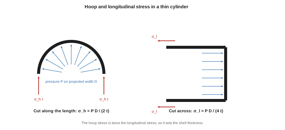
Rearranging the hoop stress relation for thickness, with the allowable stress S, the joint efficiency E and the corrosion allowance c, gives a teaching form of the shell thickness relation, often called Barlow's formula. The code's own formula adds terms that account for the thickness of the wall at high pressure and uses either the inside or the outside radius; it gives a slightly larger thickness than this teaching form at Keswold's pressure, and it is the one that must be used.
Worked problem
Teaching estimate of a drum shell thickness
Estimate the shell thickness of the teaching drum: design pressure 7.0 MPa, inside diameter 1,500 mm, allowable stress 138 MPa, joint efficiency 1.0, corrosion allowance 3 mm.
Show solution
- \[t = \frac{7.0 \times 1{,}500}{2 \times 138 \times 1.0} + 3 = 38.0 + 3 = 41.0 \text{ mm}\]
Answer: The teaching estimate is about 41 mm. The designer would then apply the code formula, add the plate's mill undertolerance, and order the next standard plate thickness, perhaps 44 or 45 mm. The estimate is useful as a check: if a drawing for a drum like this showed 20 mm or 80 mm, something would be wrong with the design conditions or the calculation.
Worked problem
Is a corroded drum still within its design?
Suppose an inspection found the teaching drum had a uniform thickness of 41 mm after corrosion, the thickness the estimate gave before the corrosion allowance was added back. What hoop stress does the design pressure produce in the remaining wall?
Show solution
- \[\sigma_h = \frac{7.0 \times 1{,}500}{2 \times 41} = 128 \text{ MPa} < 138 \text{ MPa}\]
Answer: The stress is below the allowable, so on this teaching basis the corroded wall would still carry the design pressure. A real assessment would also consider local thinning, pitting, nozzles and the code's own formula, and it would be done to a fitness-for-service standard by a qualified engineer and accepted by the inspector. The point for the chief engineer is that thickness measurements become useful only when they are compared with a minimum required thickness, which is why inspection records list both.
Spheres, heads and openings
A sphere carries pressure in two directions equally, so its stress is the same as the longitudinal stress of a cylinder of the same diameter, and it needs about half the thickness. Hemispherical heads use this, which is why they are thinner than the shells they close. Ellipsoidal heads, usually with a 2:1 ratio of diameter to depth, are deeper than flat heads but shallower than hemispheres and come out roughly as thick as the shell. Torispherical heads (flanged and dished) are shallower and need more thickness, and flat heads and covers carry pressure in bending and must be much thicker still. Each has its own code formula.
Every opening for a nozzle, manway or tube hole removes metal that was carrying stress. The code's area replacement rules require that the metal removed be replaced within a limited zone around the opening, by extra thickness in the shell, the nozzle neck or a reinforcing pad. Rows of tube holes in a drum are handled with ligament efficiency, the ratio of the metal left between holes to the pitch, which takes the place of the joint efficiency in the shell relation; Cantwell's steam drums have a ligament efficiency of about 0.45 (PWR-220), which is why their tube-sheet region is much thicker than the rest of the drum would need.
External pressure
Parts under external pressure, such as the furnace of a firetube boiler, a vessel under vacuum or a tube with steam outside it, fail by buckling rather than by yielding. The thickness needed depends on the diameter, the length between supports and the material's stiffness, and the code uses charts of geometry and material factors rather than a simple stress formula. Stiffening rings, corrugated furnaces and short unsupported lengths are the designer's tools. An important practical consequence is that a vessel designed only for internal pressure can collapse if it is accidentally put under vacuum, for example when steam condenses inside a closed tank; that is why the deaerator at Cantwell has a vacuum breaker as well as a relief valve (PWR-340).
Temperature and allowable stress
Allowable stresses come from the material's tensile and yield strengths at temperature, divided by safety factors that the code sets, and at high temperatures from its creep strength. For carbon steel, the allowable stress falls slowly up to a few hundred degrees and then steeply once creep begins, typically above about 400 °C (750 °F). Above that, low alloy steels such as 1¼ chromium-½ molybdenum and 2¼ chromium-1 molybdenum, and at higher temperatures still the advanced chromium steels and stainless steels, are used for superheaters, headers and main steam piping. Materials for high temperature service were covered in PWR-340; here the point is that the design temperature is as important as the design pressure, and that running hotter than the design temperature uses up life even when the pressure is normal (lesson 8).
Thermal stress
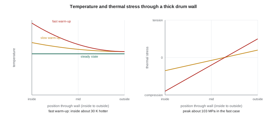
When a thick wall is heated from one side, the hot face wants to expand more than the cool face and is held back by it, producing compressive stress on the hot side and tensile stress on the cool side. For a wall fully restrained against bending, a teaching relation for the peak stress is the elastic modulus times the coefficient of expansion times the temperature difference, divided by one minus Poisson's ratio. The stress depends on the temperature difference, not on the temperature itself, which is why warm-up rates are limited by the rate of change of saturation temperature in a drum, not by the pressure.
Worked problem
Thermal stress in a drum wall
During a fast warm-up, the inside surface of a thick drum is 30 K hotter than the outside. Take E as 200 GPa, α as 12 × 10⁻⁶ per K and ν as 0.3 (typical values for carbon steel). Estimate the peak thermal stress.
Show solution
- \[\sigma_{th} \approx \frac{200{,}000 \times 12 \times 10^{-6} \times 30}{0.7} = 103 \text{ MPa}\]
Answer: About 103 MPa, which is of the same order as the pressure stress in the wall. Added together at the wrong moment, at a nozzle where stresses concentrate, the two can exceed what the material tolerates for many cycles. That is why drum and header warm-up rates are limited, typically to a few kelvin per minute of saturation temperature, and why a fast start counts as more fatigue damage than a slow one.
Fatigue and cycling
Each start, stop and large load change applies a cycle of pressure and thermal stress. A part that would last indefinitely at steady load can crack after enough cycles of a large enough range, starting at a stress concentration such as a nozzle corner, a weld toe or a tube-to-header joint. Designers of cycling plants use the code's fatigue rules, which compare the stress range of each type of cycle with a design curve giving the allowable number of cycles. A simple way to combine different cycles is the linear damage rule, often called Miner's rule: each cycle uses up the fraction one over the allowable number of cycles at its stress range, and failure is expected when the fractions add up to one.
Worked problem
How cycling changes the life of a nozzle
A drum nozzle's design analysis allows 20,000 hot starts and 3,000 cold starts. Keswold runs as a base-loaded cogeneration plant, with about 25 hot starts and 5 cold starts a year. What fraction of the nozzle's fatigue life is used each year, and what would happen if the plant were cycled daily, with 300 hot starts and 5 cold starts a year?
Show solution
- \[D_{base} = \frac{25}{20{,}000} + \frac{5}{3{,}000} = 0.00125 + 0.00167 = 0.0029 \text{ per year}\]
- \[D_{daily} = \frac{300}{20{,}000} + \frac{5}{3{,}000} = 0.0150 + 0.0017 = 0.0167 \text{ per year}\]
Answer: At base load the nozzle uses about 0.3 in 100 of its fatigue life a year, so fatigue is not what limits its life. Cycled daily, it would use about 1.7 in 100 a year, a life of about 60 years on paper, but with much less margin, and real damage concentrates at the worst details. Many combined cycle plants built for base load have been cycled hard as grids changed, and cracking at drum nozzles, superheater headers and attemperators followed. A chief engineer whose plant's duty changes must ask whether the design analysis still holds.
Tests, fitness for service and design by analysis
A new vessel is proven by a hydrostatic test at a pressure above its MAWP, set by the code (commonly about one and a half times for boilers), which checks strength and tightness while the stored energy of water is low. Repairs and alterations may also require a test, as Cantwell's boiler 3 tube repair did in November (PWR-220). A test proves the vessel on the day; it says nothing about fatigue cracks that may grow later, which is why inspection programs look for them.
When a part does not meet the simple rules, two more advanced routes exist. Design by analysis, as in Section VIII Division 2, uses detailed stress analysis, often by finite element methods, to classify stresses and compare them with limits, allowing thinner or more complex designs. Fitness-for-service assessment, as in API 579-1/ASME FFS-1, evaluates whether a part with a flaw, such as local thinning, pitting, a crack or a bulge, can safely continue in service, for how long, and at what pressure. Both require qualified engineers, and in a jurisdiction such as Ontario the regulator or inspector must accept the result. The chief engineer's role is to recognize when one of them is needed, commission it, and make sure its conditions are followed.
Morwenna closed with a reminder. "The code is written in the blood and money of a century of boiler explosions. When you find yourself arguing that a rule shouldn't apply to your vessel, stop and ask an engineer who designs them for a living."
Common mistakes
MistakeUsing a teaching formula for a real pressure part.
InsteadUse the code's own formulas, editions and allowable stresses, done by a qualified designer and registered as required.
MistakeComparing thickness readings without a minimum required thickness.
InsteadRecord both measured and minimum required thickness so each reading can be judged.
MistakeAssuming a vessel designed for pressure will survive vacuum.
InsteadCheck external pressure capability or fit a vacuum breaker.
MistakeThinking only the design pressure matters.
InsteadDesign temperature sets the allowable stress; running hotter uses up life.
MistakeTreating a hydrostatic test as proof against later cracking.
InsteadA test proves the vessel on the day; fatigue cracks need inspection.
MistakeCycling a base-load plant without revisiting its fatigue design.
InsteadReview the design analysis when the duty changes.
Summary and key terms
- The code's formulas and the registered design govern every real pressure part; teaching relations explain the principles and check numbers.
- Design conditions include pressure, temperature, corrosion allowance and mechanical, thermal and cyclic loads.
- In a thin cylinder the hoop stress is twice the longitudinal stress, so the hoop stress sets the shell thickness; a sphere needs about half the thickness.
- Openings are reinforced by area replacement; tube rows are handled by ligament efficiency; external pressure is resisted by geometry and stiffening.
- Allowable stress falls with temperature, steeply in the creep range; thermal stress depends on temperature difference.
- Fatigue damage from cycles adds up; a change from base load to cycling can use up life many times faster.
- Design pressure
- The pressure used to design a part, set above the highest expected operating pressure.
- Maximum allowable working pressure
- The highest pressure at which a part may operate, at or above which relief devices are set.
- Corrosion allowance
- Extra thickness added to cover expected metal loss over the design life.
- Hoop stress
- Circumferential stress in a cylinder wall caused by internal pressure.
- Joint efficiency
- A factor reflecting the strength of a welded seam relative to the plate.
- Ligament efficiency
- The ratio of metal between tube holes to their pitch.
- Area replacement
- The rule that metal removed by an opening must be replaced nearby.
- Miner's rule
- A linear damage rule that adds the fractions of fatigue life used by different cycles.
- Fitness for service
- An engineering assessment of whether a flawed part can continue to operate safely.
Practice problems
Work each problem on paper first, then reveal the answer to check.
Teaching thickness for a 1,200 mm drum at 5.0 MPa with S = 138 MPa, E = 1.0, c = 3 mm?
Show answer
About 21.7 + 3 = 24.7 mm.
What is the longitudinal stress if the hoop stress is 120 MPa?
Show answer
60 MPa.
Thermal stress for ΔT = 20 K with E = 200 GPa, α = 12 × 10⁻⁶ per K, ν = 0.3?
Show answer
About 69 MPa.
A part sees 400 cycles a year against an allowable 40,000. Damage fraction per year?
Show answer
0.01.
Lesson quiz · 5 questions
Score 60% or more to complete this lesson.
Create a free account to save your progress, take quizzes and earn a certificate.