
PWR-410 · Lesson 2 of 12 · 27 min
Reheat and regenerative Rankine cycles
▶ Video coming soon A video version of this lesson is on the way.
Grazyna opened the second session by drawing the T-s diagram of a simple Rankine cycle on the whiteboard and shading the area under the feedwater heating line, from the condenser temperature up to boiling. "This is the weak part," she said. "Heat added here is added at low temperature. Every large steam plant in the world is built around two tricks for fixing it, and one trick for protecting the last stages of the turbine. Tonight we work out how much each one is worth."
This lesson analyses the ideal Rankine cycle with superheat, the reheat cycle, and the regenerative cycle with open and closed feedwater heaters, using steam properties calculated from the IAPWS-IF97 formulation as in PWR-310. It then looks at how real plants combine these features and how the turbine's isentropic efficiency changes the results.
The ideal Rankine cycle reviewed
The ideal Rankine cycle has four processes: isentropic pumping of condensate to boiler pressure (1-2 in many texts), constant-pressure heat addition in the boiler and superheater, isentropic expansion in the turbine, and constant-pressure heat rejection in the condenser. With h for specific enthalpy, the results per kilogram or pound of steam are:
Here state 1 is the turbine inlet, state 2 the turbine exhaust, and state 4 the feedwater leaving the pump. The turbine exhaust state is found from the condition that the entropy stays the same: if s₁ is less than the saturated vapour entropy at the condenser pressure, the exhaust is wet, and its quality is x = (s₁ − s_f) ÷ s_fg.
Worked problem
A simple cycle as the baseline
Steam enters a turbine at 10 MPa and 500 °C and exhausts to a condenser at 10 kPa. Find the ideal cycle efficiency and the exhaust quality.
Show solution
- From IF97: h₁ = 3,375.1 kJ/kg, s₁ = 6.5993 kJ/kg·K. At 10 kPa: h_f = 191.8 kJ/kg, v_f = 0.001010 m³/kg.
- \[x_2 = 0.793, \qquad h_2 = 2{,}089.6 \text{ kJ/kg}\]
- \[w_p = 0.001010 \times (10{,}000 - 10) = 10.1 \text{ kJ/kg}, \qquad h_4 = 201.9 \text{ kJ/kg}\]
- \[\eta = \frac{(3{,}375.1 - 2{,}089.6) - 10.1}{3{,}375.1 - 201.9} = \frac{1{,}275.3}{3{,}173.2} = 0.402\]
Answer: 0.402, with the exhaust only 0.793 dry: 207 g of every kilogram is water droplets in the last stages, far too wet for a real turbine.
Raising the boiler pressure raises the mean temperature of heat addition and the efficiency, but at a fixed superheat temperature it also moves the expansion line to the left on the T-s diagram and makes the exhaust wetter. Moisture above about 10 to 12 in 100 (typical limit) causes erosion of the last-stage blades, as Okonkwo saw on Keswold's rotor in PWR-320, and also lowers stage efficiency, roughly one point of efficiency for each point of moisture (a common rule of thumb, often called Baumann's rule). The top temperature is limited by the creep strength of the superheater tubes, steam piping and turbine materials, typically around 540 to 600 °C (1,000 to 1,100 °F) for conventional plants (typical). The reheat cycle solves the moisture problem.
The reheat cycle
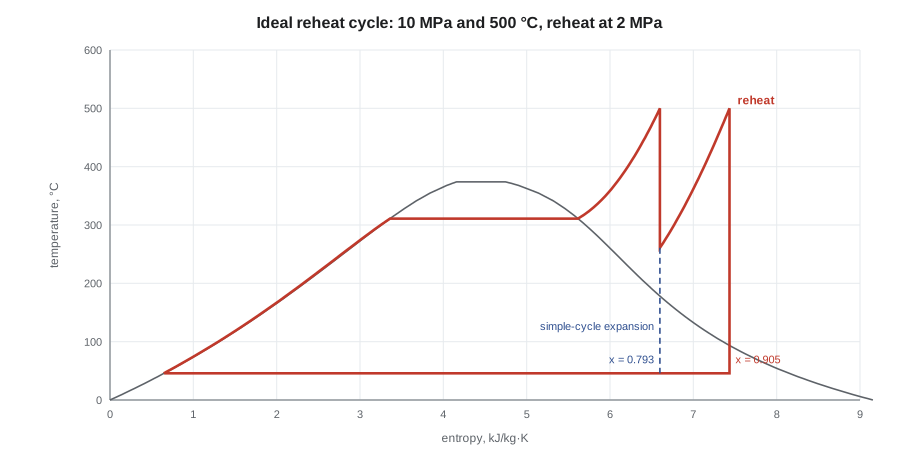
In a reheat cycle, steam expands in a high-pressure turbine to an intermediate pressure, returns to the boiler to be reheated, usually to about the original temperature, and then expands in the intermediate- and low-pressure turbines to the condenser. The extra heat is added at a high mean temperature, and the final expansion starts further to the right on the T-s diagram, so the exhaust is much drier.
Worked problem
Adding one reheat
The cycle above is modified so that steam expands to 2 MPa, is reheated to 500 °C, and expands to 10 kPa. Find the efficiency, the net work and the exhaust quality.
Show solution
- High-pressure expansion to 2 MPa at s = 6.5993: h₂ = 2,930.7 kJ/kg, slightly superheated at 260.9 °C.
- Reheat to 500 °C at 2 MPa: h₃ = 3,468.1 kJ/kg, s₃ = 7.4335 kJ/kg·K.
- Low-pressure expansion to 10 kPa: x₄ = 0.905, h₄ = 2,355.7 kJ/kg.
- \[w_t = (3{,}375.1 - 2{,}930.7) + (3{,}468.1 - 2{,}355.7) = 1{,}556.8 \text{ kJ/kg}\]
- \[q_{in} = (3{,}375.1 - 201.9) + (3{,}468.1 - 2{,}930.7) = 3{,}710.6 \text{ kJ/kg}\]
- \[\eta = \frac{1{,}556.8 - 10.1}{3{,}710.6} = 0.417\]
Answer: The efficiency rises from 0.402 to 0.417, about 3.7 parts in 100, and the net work per kilogram rises by about 21 in 100, to 1,546.7 kJ/kg, so less steam is needed for the same power. The exhaust quality improves from 0.793 to 0.905.
The best reheat pressure is usually about a fifth to a quarter of the main steam pressure (typical). Reheating at too high a pressure adds little heat and does little for the moisture; at too low a pressure the reheat heat is added at a low mean temperature and can lower the efficiency. Large utility units add a second reheat at supercritical pressures. The price of reheat is the cost of the reheater, the large reheat steam pipes, the extra valves and the controls, together with a more complicated start-up: the reheater has no steam flow until the high-pressure turbine passes steam, so it must be protected by bypass systems or by limiting the gas temperature at the reheater until flow is established.
When the turbine is not ideal, its actual exhaust enthalpy is higher than the isentropic value. With an isentropic efficiency of 0.85 for each section, the reheat cycle above gives 0.360 instead of 0.417 and an exhaust quality of 0.974, close to dry; the simple cycle gives 0.341. The ideal comparison exaggerates the absolute efficiencies but shows correctly what reheat does.
The regenerative cycle
The regenerative cycle attacks the other weakness: the low temperature at which the feedwater receives heat. Steam is extracted (bled) from the turbine at one or more intermediate pressures and used to heat the feedwater before it enters the boiler. The bled steam has already done some work in the turbine, and its latent heat, instead of being rejected in the condenser, is returned to the cycle. The boiler now receives feedwater much closer to its saturation temperature, so heat from the fuel is added at a higher mean temperature.
Feedwater heaters come in two types. An open or direct-contact feedwater heater mixes the bled steam with the feedwater; the outlet is saturated liquid at the heater pressure, and a pump is needed after each open heater. A deaerator is an open feedwater heater that also strips dissolved gases, as PWR-220 described. A closed feedwater heater is a shell-and-tube heat exchanger: feedwater flows in the tubes at full pump pressure, and the bled steam condenses on the shell side. Its condensate, the drain, is either pumped forward into the feedwater line or, more commonly, cascaded backward through a trap or level control valve to the next lower-pressure heater or the condenser.
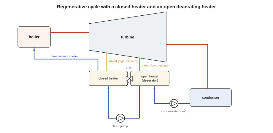
Each heater is analysed with a mass and energy balance. For one open heater, let y be the fraction of the turbine inlet flow that is bled. Per unit mass of steam entering the turbine, y kg of bled steam and (1 − y) kg of condensate from the condensate pump mix to give one kilogram of saturated liquid at the heater pressure:
where h₆ is the bled steam, h₂ the condensate leaving the condensate pump and h₃ the saturated liquid leaving the heater. The turbine work is reduced because the bled fraction does not complete its expansion:
Worked problem
One open feedwater heater
The simple cycle at 10 MPa and 500 °C with a 10 kPa condenser is given an open feedwater heater at 0.5 MPa, supplied by steam bled from the turbine. Find the bleed fraction and the ideal cycle efficiency.
Show solution
- Bled steam at 0.5 MPa, s = 6.5993: x = 0.955, h₆ = 2,654.1 kJ/kg. Exhaust h₇ = 2,089.6 kJ/kg.
- Condensate pump: h₂ = 191.8 + 0.5 = 192.3 kJ/kg. Heater outlet: saturated liquid at 0.5 MPa (151.8 °C), h₃ = 640.2 kJ/kg. Feed pump: h₄ = 640.2 + 10.4 = 650.6 kJ/kg.
- \[y = \frac{640.2 - 192.3}{2{,}654.1 - 192.3} = 0.182\]
- \[w_t = (3{,}375.1 - 2{,}654.1) + 0.818 \times (2{,}654.1 - 2{,}089.6) = 1{,}182.7 \text{ kJ/kg}\]
- \[w_p = 0.818 \times 0.5 + 10.4 = 10.8 \text{ kJ/kg}, \qquad q_{in} = 3{,}375.1 - 650.6 = 2{,}724.5 \text{ kJ/kg}\]
- \[\eta = \frac{1{,}182.7 - 10.8}{2{,}724.5} = 0.430\]
Answer: The efficiency rises from 0.402 to 0.430, about 7 parts in 100, from a single heater. The net work per kilogram falls, so the boiler and turbine must pass more steam for the same output, but the condenser receives only 0.818 kg for each kilogram entering the turbine, and its heat load per kilogram of throttle steam falls by nearly a fifth.
Closed heaters and cascaded drains
In an ideal closed heater the feedwater leaves at the saturation temperature of the bled steam. A real heater cannot quite reach it, and two temperature differences describe its performance. The terminal temperature difference (TTD) is the saturation temperature of the extraction steam minus the feedwater outlet temperature, typically about 3 K (5 °F) for a heater without a desuperheating zone (typical). The drain cooler approach (DCA) is the drain outlet temperature minus the feedwater inlet temperature, typically about 5 to 6 K (10 °F) for a heater with a drain cooling zone (typical). A rising TTD shows fouled tubes, air accumulation or a high water level flooding tubes; a falling DCA, toward zero, often means the drain cooler zone has lost its water seal, so steam is blowing through it.
Where the drain goes matters. If the drain of a closed heater were throttled directly to the condenser, its heat would be thrown away, and in the example below the cycle would actually be slightly less efficient than with no heater at all. Cascading the drain to an open heater, or pumping it forward, keeps its heat in the cycle.
Worked problem
A closed heater with its drain cascaded to the deaerator
The cycle with the open heater at 0.5 MPa is given a closed heater supplied by steam bled at 2 MPa, placed after the feed pump. The feedwater leaves the closed heater at 212.4 °C, the saturation temperature at 2 MPa (TTD zero), and the drain, saturated liquid at 2 MPa, is cascaded to the open heater. Find the two bleed fractions and the efficiency.
Show solution
- Bled steam to the closed heater: h = 2,930.7 kJ/kg. Drain: h_f at 2 MPa = 908.6 kJ/kg. Feedwater enters at 650.6 kJ/kg and leaves at 911.4 kJ/kg.
- \[y = \frac{911.4 - 650.6}{2{,}930.7 - 908.6} = 0.129\]
- Open heater balance, with the drain entering at 908.6 kJ/kg:
- \[0.129 \times 908.6 + z \times 2{,}654.1 + (1 - 0.129 - z) \times 192.3 = 640.2 \quad\Rightarrow\quad z = 0.144\]
- \[w_t = (3{,}375.1 - 2{,}930.7) + 0.871 \times (2{,}930.7 - 2{,}654.1) + 0.727 \times (2{,}654.1 - 2{,}089.6) = 1{,}095.4 \text{ kJ/kg}\]
- \[\eta = \frac{1{,}095.4 - 10.7}{3{,}375.1 - 911.4} = 0.440\]
Answer: 0.440 with two heaters, against 0.430 with one and 0.402 with none. The same closed heater with its drain dumped to the condenser would give only 0.398.
Each additional heater adds less than the one before. Large utility units have seven or eight heaters, giving final feedwater temperatures of about 250 to 290 °C (480 to 550 °F) (typical); industrial plants and cogeneration plants often have only a deaerator and one or two high-pressure heaters, because the capital cost of more heaters is not repaid at their size and running hours. In a combined cycle the situation is different: the heat comes from gas turbine exhaust that would otherwise go up the stack, so feedwater heating by extraction would raise the stack temperature and recover less heat. Keswold, as PWR-320 described, preheats its feedwater in a coil at the cold end of the heat recovery steam generator instead.
| Cycle (ideal, 10 MPa, 500 °C, 10 kPa) | Efficiency | Exhaust quality |
|---|---|---|
| Simple | 0.402 | 0.793 |
| Reheat at 2 MPa | 0.417 | 0.905 |
| One open heater at 0.5 MPa | 0.430 | 0.793 |
| Open heater plus closed heater at 2 MPa, drain cascaded | 0.440 | 0.793 |
| Closed heater at 2 MPa, drain to condenser | 0.398 | 0.793 |
| Reheat, turbine sections 0.85 efficient | 0.360 | 0.974 |
Operating the heaters
Feedwater heaters affect operation in ways that show up in a plant's logs. When a high-pressure heater is taken out of service, the feedwater reaches the economizer colder, so the boiler must fire harder for the same steam, and in a reheat unit the extraction steam that is no longer bled passes on through the later stages, which may then be overloaded; turbine makers set limits on output with heaters out of service. A heater tube leak floods the shell, and the most serious hazard of a closed heater is water induction: if the drain level rises into the extraction pipe, water can flow back into the turbine when the load falls, causing thrust bearing failures and cracked casings. Extraction lines therefore have non-return valves, often power-assisted, that close on a turbine trip or a high heater level, and heater level alarms are among the alarms that must never be ignored. PWR-320 described the trip test at Keswold in which the air solenoid of an extraction non-return valve was found faulty and replaced before start-up.
Pilar remembered a heater at a pulp mill where she had worked a summer as a student, which had been bypassed for months because its level controller was unreliable. "So the boiler burned extra fuel every hour of those months," Grazyna said. "Put a number on it next time someone asks you to bypass a heater." Pilar did: by her rough reckoning from the table, losing a single high-pressure heater in a plant of that kind costs on the order of one to three points of cycle efficiency (typical), several hundred thousand dollars a year in fuel at a mill's steam rates.
Common mistakes
MistakeReheating to raise the efficiency at any reheat pressure.
InsteadThe benefit depends on the reheat pressure; too low a reheat pressure can lower the efficiency.
MistakeDumping closed heater drains to the condenser without counting the loss.
InsteadCascade drains to the next heater or pump them forward; throttling them to the condenser wastes their heat.
MistakeForgetting that bled steam does less work.
InsteadThe turbine work falls with bleeding; the gain comes from adding less heat at low temperature.
MistakeIgnoring heater levels because the heater still heats.
InsteadHigh levels flood tubes, raise the TTD and risk water induction into the turbine.
MistakeExpecting extraction feedwater heating to help a combined cycle.
InsteadIt raises the HRSG stack temperature; combined cycles heat feedwater with exhaust gas instead.
Summary and key terms
- Reheating raises the mean temperature of heat addition and, above all, dries the turbine exhaust.
- Regeneration heats feedwater with bled steam, so less heat is added at low temperature.
- Open heaters mix streams and need a pump after them; closed heaters are heat exchangers with drains.
- The bleed fraction comes from an energy balance on each heater: y = (h_out − h_in) ÷ (h_bleed − h_drain).
- Terminal temperature difference and drain cooler approach measure closed heater performance.
- Extraction non-return valves and heater level controls protect the turbine from water induction.
- Reheat cycle
- A Rankine cycle in which steam is returned to the boiler after partial expansion and reheated.
- Regenerative cycle
- A Rankine cycle in which steam bled from the turbine heats the feedwater.
- Open feedwater heater
- A heater in which bled steam mixes directly with the feedwater.
- Closed feedwater heater
- A shell-and-tube heater in which bled steam condenses on the outside of tubes carrying feedwater.
- Terminal temperature difference
- The saturation temperature of the heater steam minus the feedwater outlet temperature.
- Drain cooler approach
- The drain outlet temperature minus the feedwater inlet temperature of a closed heater.
- Cascading drains
- Passing heater condensate to the next lower-pressure heater through a trap or level valve.
- Water induction
- The return of water from a heater or extraction line into a turbine, causing severe damage.
Practice problems
Work each problem on paper first, then reveal the answer to check.
An open heater receives condensate at 192.3 kJ/kg and bled steam at 2,700 kJ/kg and delivers saturated liquid at 561.5 kJ/kg. Find the bleed fraction.
Show answer
y = (561.5 − 192.3) ÷ (2,700 − 192.3) = 0.147.
A heater's steam is at 2 MPa (T_sat 212.4 °C) and the feedwater leaves at 208.9 °C. What is the TTD?
Show answer
3.5 K.
A turbine section expands steam from 3,375 kJ/kg to an isentropic 2,931 kJ/kg with an efficiency of 0.85. Find the actual outlet enthalpy.
Show answer
3,375 − 0.85 × 444 = 2,998 kJ/kg.
A cycle's efficiency rises from 0.402 to 0.430. By what fraction does fuel for the same output fall?
Show answer
1 − 0.402 ÷ 0.430 = 0.065.
Lesson quiz · 5 questions
Score 60% or more to complete this lesson.
Create a free account to save your progress, take quizzes and earn a certificate.