
PWR-230 · Lesson 11 of 12 · 29 min
Piping, valves and steam traps
▶ Video coming soon A video version of this lesson is on the way.
On Saturday, October 31, 2026, Lorne Fitzwilliam and Tamar Ellingsen spent the day in the steam tunnels and vaults with an ultrasonic trap tester, an infrared thermometer and a clipboard listing every steam trap on Cantwell's distribution mains. It was the autumn trap survey, done before the coldest months when the mains carry their heaviest load. They started at vault 4, where the bare section of main found with the thermal camera on October 21 had been insulated the week before, and worked outward. "A failed trap either wastes steam all winter or floods a main with water," Lorne said. "The first costs money. The second can kill somebody."
This lesson covers the piping that carries steam, water and condensate around a plant and its distribution system, the valves that control it and how to operate them, steam traps and how to test them, the cost of a failed trap, and the causes and prevention of water hammer.
Piping
Plant piping is chosen for the fluid, the pressure and the temperature it carries:
- Carbon steel pipe, seamless or welded, to ASTM A106 or A53, carries steam, condensate, feedwater and hot water. Its wall thickness is specified by schedule: Schedule 40 is standard for most services, Schedule 80 for higher pressures and for condensate lines, which corrode from the inside.
- Copper tube carries domestic water, small hot water lines, instrument air and refrigerants. Stainless steel carries chemicals, demineralized water and some condensate. Ductile iron and plastic pipes carry cold water and drains.
Joints are welded (butt-welded or socket-welded) for steam and high-pressure service, flanged where equipment must be removed, threaded only on small, lower-pressure lines, and grooved with mechanical couplings on water systems.
Pressure piping is designed and built to the ASME B31 codes, mainly B31.1 Power Piping for boiler external piping and high-pressure steam, and B31.9 Building Services Piping for lower-pressure building systems. In Ontario, O. Reg. 220/01 and CSA B51 require pressure piping systems above set limits to be designed, registered and installed under TSSA's rules, and repairs and alterations to them done by authorized contractors.
Piping must be supported so it does not sag and trap water, anchored where it must not move, and allowed to expand elsewhere through loops, bends or expansion joints, as PWR-210 lesson 5 showed for the tunnel expansion loop. Hot lines are insulated, both to save energy and to protect people; the bare section in vault 4 was losing heat at a rate PWR-210 lesson 8 estimated in kilowatts.
Piping is identified by labels or colour bands showing its contents and direction of flow, so that an operator can tell a steam line from a condensate line at a glance, even in a dark vault.
Valves
Each kind of valve has a job it does well and jobs it does badly:
- Gate valves have a wedge or disc that slides across the flow. Fully open, they offer almost no resistance; they are for isolation, open or shut, not for throttling. A partly open gate valve vibrates and its seats are cut by the high-velocity flow.
- Globe valves have a disc that closes down onto a seat, with the flow turning through the body. They throttle well, and are used for control, bypasses and drains, at the cost of a higher pressure drop.
- Ball valves turn a drilled ball a quarter turn from open to shut. They are quick, tight and compact; standard ones are for isolation, not throttling.
- Butterfly valves turn a disc a quarter turn. They are light and cheap for large water lines, and high-performance types with offset discs serve steam and throttling duties.
- Plug valves turn a tapered or cylindrical plug, often for fuel gas and slurries.
- Check valves let flow pass one way only. Swing checks have a hinged disc, lift checks a disc that rises off a seat, wafer or dual-plate checks fit between flanges. Every pump in parallel with another needs one on its discharge.
- Pressure-reducing valves hold a lower downstream pressure, as in the Ardoch Tower PRV station in PWR-120 lesson 10.
- Control valves, usually globe or rotary valves with actuators, are positioned by the control system.
- Safety valves and relief valves, covered in PWR-220, protect against overpressure and are never used for anything else.
A valve's flow capacity is given by its flow coefficient. In US practice, Cv is the flow of water in US gallons per minute that the valve passes with a pressure drop of 1 psi; in metric practice, Kv is the flow in m³/h with a drop of 1 bar. Kv is about 0.865 times Cv. For water, flow rises with the square root of the pressure drop:
with Q in m³/h and Δp in bar.
Worked problem
Flow through a bypass valve
A valve has Kv = 21.6 (Cv = 25). How much water does it pass with a pressure drop of 1.72 bar (172 kPa)?
Show solution
- \[Q = 21.6 \sqrt{1.72} \approx 21.6 \times 1.31 \approx 28.3 \text{ m}^3\text{/h}\]
Answer: About 28.3 m³/h, about 7.9 L/s. Doubling the pressure drop would raise the flow by only about 41 in 100, because of the square root.
Operating valves on steam
- Open steam valves slowly. A main valve opened quickly onto a cold or wet line sends a slug of steam and water down it and can cause water hammer. Large valves have a small warm-up bypass valve that is opened first to warm and pressurize the downstream side.
- Before admitting steam to a line, open its drains and warm it gradually, blowing condensate out until steam appears.
- Open gate valves fully, then, on hot service, back them off a fraction of a turn so they do not bind as the stem and body expand. Some plants mark the position so other operators know it is fully open.
- Never use a cheater bar or wrench on a handwheel beyond what the valve is designed for. A valve that will not close tightly by hand needs maintenance, not force: extra torque bends stems and cracks bodies.
- Stand to the side of a valve when operating it, not in front of the bonnet or packing, and wear gloves; hot packing glands can spray.
- Know which way the valve closes and where it is. Valves on the plant's isolation lists are tagged with numbers matching the drawings, so a lockout names exactly the right valve.
Valve packing on a hot stem is adjusted the same way as pump packing, a little at a time and evenly. Valves that leak through their seat when closed are reported: they cannot be trusted for isolation, and a lockout that depends on one needs a second valve or a blank.
Steam traps
As steam gives up heat in a main, a heat exchanger or a coil, some of it condenses. That condensate must be removed, because it blocks heat transfer, corrodes the pipe and, if it builds up in a main, can be picked up by fast-moving steam and thrown as a slug. Air and other non-condensable gases must also be removed, especially at start-up, because they blanket heat transfer surfaces. A steam trap is an automatic valve that lets condensate and air out while holding steam in.
Traps work on three principles:
- Mechanical traps sense the difference in density between steam and water. A float and thermostatic (F&T) trap has a float that opens a valve as condensate rises, plus a thermostatic air vent; it drains continuously and suits heat exchangers with varying loads. An inverted bucket trap has an open-bottomed bucket that floats when steam fills it and sinks to open the valve when condensate fills it; it is robust, resists water hammer and suits drip legs on mains.
- Thermostatic traps sense temperature: condensate cools slightly below steam temperature and the trap opens. Balanced pressure traps use a capsule filled with a liquid that boils just below steam temperature; bimetallic traps use strips that bend as they cool. They vent air well and suit tracers and start-up loads, but they hold condensate back until it cools.
- Thermodynamic or disc traps use the different flow behaviour of flash steam and condensate under a small disc. They are compact, tolerant of superheat and water hammer, and suit drip legs and tracers, but they cycle with a distinctive click and waste a little steam.
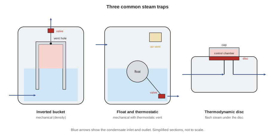
Every trap station should have a strainer ahead of the trap, isolation valves on both sides, a test valve or sight glass downstream, and often a check valve where the trap discharges into a return line at higher pressure. On steam mains, condensate is collected in drip legs: short vertical pockets of full pipe diameter at low points and at intervals along the main, with the trap connection a little above the bottom so dirt settles below it.
Testing traps
Traps fail in two ways:
- Failed open (blowing): live steam passes straight through. The trap and its discharge are very hot, the ultrasonic tester hears a continuous rush, and a test valve shows steam blowing, not just flash steam.
- Failed closed (cold or blocked): condensate is not removed. The trap and its inlet line are cooler than they should be, and the ultrasonic tester hears nothing. Upstream, the main or the exchanger fills with water.
Testing combines methods:
- Temperature, with an infrared thermometer or contact probe on the inlet and outlet. A trap much cooler than the saturation temperature of the line is probably blocked.
- Ultrasound, listening at the trap body for its operating cycle: the regular open-close of a bucket or disc trap, the steady quiet flow of an F&T trap. Continuous high-pitched rushing means steam is passing.
- Visual, at a test valve or into an open discharge: condensate with lazy wisps of flash steam is normal; a strong, clear jet of steam near the outlet means the trap is blowing. Flash steam always appears when hot condensate drops to atmospheric pressure, and mistaking it for blowing steam is the most common error in trap surveys.
Lorne and Tamar tested 42 traps. Three were blowing, including one on a drip leg near vault 2 whose disc had worn, and two were cold. One of the cold ones, at the low point of the main in vault 6, worried Lorne: its strainer was packed solid with scale, and the drip leg above it was full to the top. He opened the drip leg's blowdown valve slowly, standing well to the side, and let the water drain to the vault sump until steam appeared, then left the bypass cracked under watch until Fenella's crew could clear the strainer that afternoon. The other cold trap had simply been isolated after the summer's work and never put back in service. Every result went on the survey sheet with a tag number, and the three blowing traps were scheduled for replacement within the week.
What a failed trap costs
Steam blowing through a failed-open trap can be estimated with Napier's formula for steam flowing through an orifice at a pressure high enough that the flow is choked:
with W in kg/h, P the upstream pressure in kPa absolute and D the orifice diameter in mm.
This gives the flow of dry steam through a clean orifice of that size, an upper estimate. A real failed trap often passes some condensate too, or has worn only partly open, so surveyors usually treat the result as the worst case.
Worked problem
Steam lost through one failed trap
A trap on a main at 1,035 kPa gauge (1,136 kPa absolute) has failed fully open through its 4.76 mm orifice. Estimate the steam lost, and the yearly cost if the main is in service 8,000 hours a year. Each kilogram of steam took 2,342 kJ to make from feedwater, the boilers are 0.82 efficient, natural gas gives 37.3 MJ/m³, and the sample gas price is 30 cents per m³.
Show solution
- Steam flow:
- \[W \approx 0.00247 \times 1{,}136 \times 4.76^2 \approx 63.6 \text{ kg/h}\]
- Steam per year:
- \[63.6 \times 8{,}000 \approx 509{,}000 \text{ kg}\]
- Fuel energy:
- \[509{,}000 \times 2{,}342 \div 0.82 \approx 1{,}454{,}000{,}000 \text{ kJ} = 1{,}454 \text{ GJ}\]
- Gas and cost:
- \[1{,}454{,}000 \text{ MJ} \div 37.3 \approx 39{,}000 \text{ m}^3 \to 39{,}000 \times 0.30 \approx 11{,}700 \text{ dollars}\]
Answer: Up to about 64 kg/h of steam and roughly 11,700 dollars a year at the sample price, for a trap that costs a few hundred dollars to replace. Three such failures would waste more than a typical trap survey costs many times over, which is why plants survey their traps at least once a year and districts with large distribution systems more often.
Lost steam is also lost water and treatment chemicals, and a blowing trap pressurizes the condensate return, which can stop other traps from draining.
Water hammer
Water hammer is the shock that occurs when moving water is stopped suddenly or when slugs of water are driven by steam. It ranges from a harmless knock to a pressure spike that splits fittings, blows gaskets and ruptures pipe. Steam system water hammer has killed and badly scalded operators and passers-by, often within seconds of a valve being opened.
There are three main kinds:
- Hydraulic shock in liquid lines: a valve closed quickly or a pump tripping stops a moving column of water, and the pressure rises sharply.
- Steam-driven slug flow: condensate collects in a low point of a steam main, the fast-moving steam picks it up as a slug and drives it down the line at steam velocity until it hits an elbow, a valve or a tee.
- Condensation-induced water hammer: steam flows over cold condensate lying in a line, or is admitted to a line partly full of water. Steam condenses rapidly against the cold water, its volume collapses, and the water rushes in to fill the void and slams together. This kind produces the highest pressures and has caused the worst accidents, often in lines being returned to service after a shutdown, or where a trap has failed closed and the line has filled.
The pressure rise when a column of water is stopped suddenly can be estimated with the Joukowsky equation:
where ρ is the density, a the speed of a pressure wave in the water in the pipe and Δv the change in velocity.
Worked problem
Pressure rise from a sudden stop
Water (1,000 kg/m³) flowing at 2 m/s in a steel pipe is stopped instantly by a fast-closing valve. The pressure wave travels at about 1,400 m/s. What pressure rise results?
Show solution
- \[\Delta p = 1{,}000 \times 1{,}400 \times 2 = 2{,}800{,}000 \text{ Pa} = 2{,}800 \text{ kPa}\]
Answer: About 2,800 kPa, nearly three times the steam header pressure, from water moving at walking pace. Slowing the closure, so that the valve takes longer to close than a pressure wave takes to travel to the end of the pipe and back, greatly reduces the rise.
Steam system water hammer is prevented by keeping condensate out of steam lines and steam away from standing water:
- Slope steam mains in the direction of flow, typically by about 1 in 240, and fit drip legs and traps at every low point, before risers, before control valves and at intervals along long runs.
- Keep traps working and strainers clean, and survey them regularly.
- Warm lines slowly with drains open before admitting full steam, using warm-up bypasses on large valves.
- Never open a steam valve into a line that may contain water without first draining it. If water hammer starts, close the valve slowly to stop the steam flow, drain the line, and then begin again slowly; do not open further to "push it through".
- Size condensate return lines for flashing two-phase flow, and lift condensate only from traps where the pressure allows it.
- Use slow-closing valves and surge protection on long liquid lines, and check valves that close without slamming.
Lorne's caution with the flooded drip leg in vault 6 was exactly that rule in action: drain the water slowly, from the side, before letting steam move it.
Common mistakes
MistakeThrottling flow with a gate valve.
InsteadUse a globe or control valve; a partly open gate valve vibrates and its seats wear.
MistakeOpening a main steam valve quickly onto a cold line.
InsteadWarm slowly through the bypass with drains open.
MistakeMistaking flash steam from a trap discharge for a blowing trap.
InsteadFlash steam is lazy and appears away from the outlet; live steam is a clear jet at the outlet.
MistakeForcing a valve shut with a cheater bar.
InsteadReport it; extra torque bends stems and cracks bodies.
MistakeOpening a steam valve further to push through water hammer.
InsteadClose it slowly, drain the line, then start again slowly.
Summary and key terms
- Plant piping is carbon steel for steam and condensate, built to ASME B31.1 or B31.9 and the jurisdiction's registration rules; it is supported, anchored, allowed to expand and insulated.
- Gate and ball valves isolate; globe valves throttle; check valves stop backflow; Cv and Kv rate a valve's capacity, with flow rising with the square root of pressure drop.
- Steam traps remove condensate and air: mechanical traps sense density, thermostatic traps temperature, thermodynamic traps flow behaviour.
- Traps fail open (blowing steam) or closed (flooding); temperature, ultrasound and sight tests find them.
- Napier's formula, W ≈ 0.00247 × P × D² kg/h, gives an upper estimate of steam through a failed trap; one trap can waste thousands of dollars a year.
- Water hammer comes from sudden stops, steam-driven slugs and condensation collapse; drainage, slope, working traps and slow warm-up prevent it.
- Schedule
- A number indicating a pipe's wall thickness for its size.
- Gate valve
- An isolation valve with a sliding wedge, used fully open or fully shut.
- Globe valve
- A valve with a disc closing onto a seat, used for throttling.
- Flow coefficient
- A valve's capacity: Cv in gpm at 1 psi drop, or Kv in m³/h at 1 bar drop.
- Steam trap
- An automatic valve that discharges condensate and air while holding back steam.
- Drip leg
- A pocket at a low point of a steam main where condensate collects for a trap to remove.
- Flash steam
- Steam formed when hot condensate is released to a lower pressure.
- Water hammer
- A pressure shock caused by stopping moving water suddenly or by slugs of water driven by steam.
- Condensation-induced water hammer
- Water hammer caused by steam condensing rapidly against cold water, letting the water slam together.
Practice problems
Work each problem on paper first, then reveal the answer to check.
A valve has Kv = 10. What water flow does it pass at a drop of 4 bar?
Show answer
20 m³/h.
Estimate the steam through a 3.2 mm orifice at 700 kPa absolute.
Show answer
About 17.7 kg/h.
Water at 1.5 m/s is stopped instantly; the wave speed is 1,300 m/s. What is the pressure rise?
Show answer
About 1,950 kPa.
A trap is much cooler than the saturation temperature of its line and silent on ultrasound. How has it failed?
Show answer
Closed or blocked.
Why is the trap connection set a little above the bottom of a drip leg?
Show answer
So dirt and scale settle below it instead of blocking the trap.
Lesson quiz · 5 questions
Score 60% or more to complete this lesson.
Create a free account to save your progress, take quizzes and earn a certificate.