
PWR-230 · Lesson 10 of 12 · 26 min
Plant refrigeration and air conditioning
▶ Video coming soon A video version of this lesson is on the way.
Shortly after midnight on Sunday, October 25, 2026, Desmond Kirwan, the night shift engineer, carried a small cylinder of calibration gas and a tubing kit into the chiller room, with Tamar Ellingsen, on her first night shift of the rotation, close behind. It was time for the monthly function test of the refrigerant monitor. "Most nights nobody comes in here," Desmond said. "If this chiller dumps its charge at three in the morning, the monitor is the only thing that knows. It has to sound the alarm, start the exhaust fan and stop anyone walking into a room full of refrigerant without warning. So once a month we make sure it does."
This lesson builds on RAC-110's refrigeration fundamentals and looks at refrigeration as a plant system: the vapour-compression cycle in a chiller, how capacity and efficiency are measured, the kinds of chillers a heating and cooling plant uses, refrigerant safety classes, and the machinery room requirements of CSA B52, including the refrigerant monitor and emergency ventilation.
The vapour-compression cycle
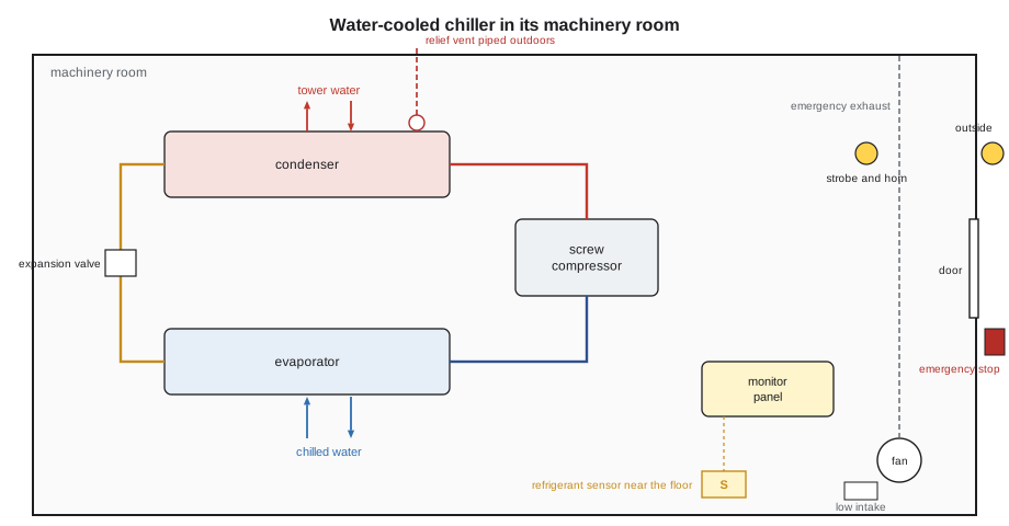
RAC-110 introduced the four parts of the vapour-compression cycle. In a water-cooled chiller like Cantwell's, they are:
- The evaporator: a shell-and-tube exchanger in which liquid refrigerant at low pressure boils, absorbing heat from the chilled water flowing through the tubes. The chilled water leaves at about 7 °C (44 °F).
- The compressor: it draws the low-pressure vapour from the evaporator and compresses it to a high pressure and temperature.
- The condenser: another shell-and-tube exchanger, in which the hot vapour condenses on tubes carrying cooling water from the tower (lesson 9), giving up the heat it absorbed plus the heat of compression.
- The expansion device: an electronic expansion valve, orifice or float valve that drops the liquid back to evaporator pressure, flashing part of it to vapour and chilling the rest.
The refrigerant carries heat from the chilled water to the cooling water, and the compressor supplies the work that lifts it from the low temperature to the high one. An energy balance on the whole chiller is simple: the heat rejected at the condenser equals the cooling done at the evaporator plus the energy put in by the compressor.
Capacity and efficiency
Refrigeration capacity is measured in kilowatts, or in tons of refrigeration in North American practice. One ton is the rate of cooling that would melt one short ton of ice in 24 hours: 12,000 Btu/h, or about 3.517 kW.
Efficiency is described in several ways:
- The coefficient of performance (COP): the cooling delivered divided by the energy input, both in the same units.
- kW per ton: the compressor's electrical input per ton of cooling, common for large chillers. Lower is better.
- EER (energy efficiency ratio): Btu/h of cooling per watt of input, used for smaller equipment.
Worked problem
Cantwell's chiller
At full load the chiller delivers 290 kW of cooling and its compressor draws 62 kW. Find its COP, its capacity in tons, its kW per ton, and the heat its condenser rejects to the cooling tower.
Show solution
- COP:
- \[290 \div 62 \approx 4.7\]
- Tons:
- \[290 \div 3.517 \approx 82.5 \text{ tons}\]
- kW per ton:
- \[62 \div 82.5 \approx 0.75 \text{ kW/ton}\]
- Heat rejected:
- \[290 + 62 = 352 \text{ kW}\]
Answer: A COP of about 4.7 and about 0.75 kW per ton, typical of a mid-size water-cooled screw chiller at full load. The condenser rejects about 352 kW, the same figure used for the cooling tower in lesson 9.
A chiller's COP rises when the lift, the difference between condensing and evaporating temperatures, is small. Colder condenser water and warmer chilled water both improve efficiency, which is why chilled water set points are reset upward in mild weather and why fouled condenser tubes, which raise the condensing temperature, waste so much energy. Most chillers are more efficient at part load than at full load, and their published part-load ratings reflect that.
Kinds of chiller
- Scroll and reciprocating compressors serve small chillers and packaged units, often several compressors staged on and off.
- Screw compressors, like Cantwell's, serve mid-size chillers from about 300 to 2,000 kW (85 to 570 tons). Capacity is controlled by a slide valve or by speed.
- Centrifugal compressors serve large chillers, from a few hundred to several thousand tons, with inlet guide vanes or variable speed for capacity control. Some modern units use magnetic bearings and need no oil.
- Absorption chillers use heat instead of a compressor. In a lithium bromide unit, water is the refrigerant: it evaporates at very low pressure in the evaporator, is absorbed by a concentrated lithium bromide solution, and is driven out of the solution again by heat from steam, hot water or a burner in the generator. Single-effect steam absorption chillers have a COP of about 0.7; double-effect units about 1.2. District energy plants often use them in summer because they turn steam, which the plant has in surplus, into cooling.
Large district energy systems also produce chilled water centrally and distribute it, sometimes with thermal storage in tanks of chilled water or ice. Cantwell's chiller is small and serves only the plant itself.
Refrigerants and their safety classes
Refrigerants are classified for safety by ASHRAE Standard 34, which CSA B52 and the building codes refer to. Each refrigerant gets a letter for toxicity and a number for flammability:
- A means lower toxicity; B means higher toxicity.
- 1 means no flame propagation; 2L lower flammability with a low burning velocity; 2 flammable; 3 higher flammability.
| Refrigerant | Safety class | Typical use |
|---|---|---|
| R-134a | A1 | Screw and centrifugal chillers (being phased down) |
| R-513A | A1 | Lower-GWP replacement for R-134a in chillers |
| R-1234ze(E) | A2L | Low-GWP chillers |
| R-410A | A1 | Rooftop units and split systems (being phased down) |
| R-454B, R-32 | A2L | Newer rooftop units and split systems |
| R-717 (ammonia) | B2L | Industrial refrigeration and ice rinks |
| R-123 | B1 | Older low-pressure centrifugal chillers |
An A1 refrigerant such as R-134a is neither toxic nor flammable in normal use, but it is still dangerous in a large leak. It is about three and a half times heavier than air, so it sinks and pools in low places, and in high concentrations it displaces oxygen and can cause heart irregularities and death without much warning. Refrigerant that touches a hot surface or flame can break down into toxic and corrosive products.
Many older refrigerants are being phased down because of their global warming potential, under the Kigali Amendment to the Montreal Protocol and, in Canada, the federal Ozone-depleting Substances and Halocarbon Alternatives Regulations. Anyone who handles refrigerants must hold the required training certificate, such as the environmental awareness training that Canadian provinces require, and work on refrigeration systems is done by licensed refrigeration mechanics. The plant operator's job is to run the system, watch for leaks and keep records.
Machinery rooms
A machinery room is a room built to house refrigerating equipment safely. CSA B52, the Mechanical Refrigeration Code, adopted in Ontario through TSSA's boilers and pressure vessels code adoption document, (ASHRAE Standard 15, Safety Standard for Refrigeration Systems, adopted through the mechanical code,) requires one when the amount of refrigerant in a system is too large to release safely into an occupied space, which in practice includes most chillers. The main requirements are:
- Construction: tight-fitting, self-closing doors that open outward, no openings that would let refrigerant escape into other parts of the building, and signs at the entrance identifying the room as a refrigerating machinery room for authorized personnel only.
- Refrigerant detection: at least one detector, placed where refrigerant will collect, near the floor for refrigerants heavier than air such as R-134a, near the ceiling for lighter ones such as ammonia. The detector must activate an alarm and the emergency ventilation at a concentration no higher than the refrigerant's occupational exposure limit (OEL), which is 1,000 ppm for R-134a.
- Alarms: audible and visual alarms inside the room and outside each entrance, so no one walks in during a leak.
- Emergency ventilation: mechanical exhaust sized for the largest system in the room, started automatically by the detector and also by a switch outside the room. The exhaust intake is low for heavy refrigerants and the discharge goes outdoors away from openings.
- Emergency shutdown: a clearly identified switch outside the room, next to the main door, that stops the refrigerant compressors.
- Relief valves on the chiller, piped to discharge outdoors, never into the room.
- No open flames or hot surfaces above set limits in the room, since they decompose refrigerant into toxic products.
The emergency exhaust is sized from the refrigerant charge. The formula in ASHRAE 15, also used widely in Canada, is:
with Q in L/s and G the charge of the largest system in the room, in kilograms.
Worked problem
Exhaust needed for the chiller room
Cantwell's chiller holds 95 kg of R-134a and is the only system in the room. What emergency exhaust rate does the formula give?
Show solution
- \[Q = 70 \sqrt{95} \approx 70 \times 9.75 \approx 682 \text{ L/s}\]
Answer: About 682 L/s, about 1,450 cfm. The room's emergency fan is rated above that, and the fan and its low intake grille are checked during the monitor test.
Worked problem
How little refrigerant reaches the alarm level?
The chiller room is 12 m × 8 m × 4 m. If the whole 95 kg charge of R-134a (molar mass 102 g/mol) mixed evenly into the room, what concentration would result, in ppm by volume? How much refrigerant, evenly mixed, would reach the OEL of 1,000 ppm? Take 24.45 L/mol for a gas at room conditions.
Show solution
- Room volume:
- \[12 \times 8 \times 4 = 384 \text{ m}^3\]
- Concentration by mass:
- \[95{,}000{,}000 \text{ mg} \div 384 \approx 247{,}000 \text{ mg/m}^3\]
- Convert to ppm by volume:
- \[247{,}000 \times \frac{24.45}{102} \approx 59{,}000 \text{ ppm}\]
- Refrigerant to reach 1,000 ppm:
- \[95 \times \frac{1{,}000}{59{,}000} \approx 1.6 \text{ kg}\]
Answer: A full release would give about 59,000 ppm, nearly 6 in 100 of the air, even if it mixed evenly, and in reality the heavy gas would pool much deeper near the floor. Only about 1.6 kg, less than 2 in 100 of the charge, is enough to reach the alarm level. That is why the monitor matters even for a non-toxic, non-flammable refrigerant.
The monitor test
Desmond followed the plant's procedure, which is based on the monitor manufacturer's instructions. He told the control room the test was starting, so that the alarm would not be treated as real, and checked that no one else was in the chiller room. With the monitor showing its normal background reading near zero, he fitted the calibration cap over the sensor near the floor behind the chiller and released a short flow of test gas from the cylinder.
The reading climbed steadily. At the alarm set point the horn sounded and the strobe flashed inside the room, Tamar confirmed by radio that the strobe and horn outside the door were working, and the emergency exhaust fan started with a roar. Desmond checked that the exhaust damper had opened and that air was moving through the low intake grille. He removed the test gas, let the reading fall back, reset the alarm and confirmed the fan returned to normal. He also pressed the outside ventilation switch to prove it started the fan by hand, and checked that the emergency shutdown switch by the door was clearly labelled and unobstructed, without operating it, since it would have stopped the chiller serving the control room.
Everything worked, but the reading had taken noticeably longer to climb than on the last two monthly tests. Desmond noted the response time on the log and flagged it for Grazyna. The sensor is due for calibration by the monitor's service contractor, who calibrates it twice a year and replaces sensors at the end of their rated life; Grazyna booked the next calibration visit for December and asked the contractor to check that sensor specifically.
The monthly function test proves that the alarm and the ventilation work; the contractor's calibration with certified gas proves that the reading is accurate. Both are needed.
Operating a chiller
The daily log for a chiller records the readings that reveal its condition:
- Chilled water and condenser water temperatures in and out, and their flows or pressure drops.
- Evaporator and condenser refrigerant pressures and saturation temperatures, and the approach of each: the difference between the leaving water temperature and the refrigerant saturation temperature. A rising condenser approach means fouled tubes or air in the condenser; a rising evaporator approach can mean fouling or low refrigerant charge.
- Compressor discharge temperature, oil pressure and oil temperature, motor current and percentage load.
- Alarms and any refrigerant monitor readings.
Chillers have their own safety controls: low evaporator pressure or low chilled water temperature to prevent the tubes freezing, which can split them; high condenser pressure; flow switches that stop the compressor if water flow is lost; motor overloads; and oil pressure protection. Never bypass a flow switch or freeze protection to keep a chiller running. A frozen evaporator lets water into the refrigerant circuit and can wreck the machine.
Leaks show up as falling charge, bubbles in a liquid line sight glass, oil spots at joints, or rising monitor readings. Most jurisdictions require large systems to be leak-checked on a schedule and records kept of refrigerant added and recovered.
Air conditioning in the plant
Comfort cooling and ventilation in the plant's offices, control room and electrical rooms come from air handling units with chilled water coils fed by the chiller, plus a few packaged rooftop units and split systems with their own refrigerant circuits. Operators check air handlers for filter differential pressure, coil condition, condensate drain flow (a blocked drain pan overflows and grows mould), belt condition and damper operation. In winter the economizer dampers bring in outdoor air for free cooling of the electrical rooms, which keeps the chiller's winter load small.
Common mistakes
MistakeTreating a non-toxic, non-flammable refrigerant leak as harmless.
InsteadLarge leaks displace oxygen and can cause heart problems; evacuate, ventilate and let the monitor clear before entering.
MistakeEntering a machinery room when the refrigerant alarm is sounding.
InsteadStay out, start the ventilation from outside, and follow the emergency procedure.
MistakeTesting the alarm but not the ventilation.
InsteadThe function test must prove the alarm, the strobes inside and out, and the exhaust fan.
MistakeBypassing a chiller flow switch to keep it running.
InsteadNever; loss of flow can freeze and split the evaporator tubes.
MistakeVenting a relief valve discharge into the machinery room.
InsteadRelief valves discharge outdoors.
Summary and key terms
- A chiller moves heat from chilled water to condenser water through the evaporator, compressor, condenser and expansion device.
- One ton of refrigeration is 12,000 Btu/h or 3.517 kW; COP = cooling ÷ input; heat rejected = cooling + compressor input.
- Screw, centrifugal, scroll and absorption chillers serve plants; steam absorption chillers turn surplus steam into cooling.
- ASHRAE 34 classes refrigerants by toxicity (A or B) and flammability (1, 2L, 2, 3).
- CSA B52 machinery rooms need refrigerant detectors alarming at or below the OEL, alarms inside and out, emergency exhaust (Q = 70√G L/s), an outside shutdown switch and relief valves vented outdoors.
- A small fraction of a chiller's charge reaches the alarm level; monthly function tests and periodic calibration keep the monitor reliable.
- Vapour-compression cycle
- The refrigeration cycle of evaporation, compression, condensation and expansion.
- Ton of refrigeration
- 12,000 Btu/h, about 3.517 kW of cooling.
- Coefficient of performance
- Cooling delivered divided by energy input.
- Lift
- The difference between a chiller's condensing and evaporating temperatures.
- Absorption chiller
- A chiller that uses heat, such as steam, to drive a lithium bromide and water cycle.
- Machinery room
- A room built to house refrigerating equipment with detection, alarms and emergency ventilation.
- Occupational exposure limit
- The time-weighted concentration of a substance considered safe for repeated workplace exposure.
- Refrigerant monitor
- A detector that measures refrigerant concentration and triggers alarms and ventilation.
Practice problems
Work each problem on paper first, then reveal the answer to check.
A chiller produces 700 kW of cooling with 125 kW of input. What is its COP?
Show answer
5.6.
What is 700 kW in tons?
Show answer
About 199 tons.
What heat does that chiller reject to its cooling tower?
Show answer
825 kW.
A machinery room's largest system holds 250 kg of refrigerant. What emergency exhaust does Q = 70√G give?
Show answer
About 1,107 L/s.
Where should the sensor be for R-134a, and why?
Show answer
Near the floor, because R-134a is much heavier than air.
Lesson quiz · 5 questions
Score 60% or more to complete this lesson.
Create a free account to save your progress, take quizzes and earn a certificate.