
PLB-410 · Lesson 5 of 12 · 27 min
Complex water supply sizing problems
Drainage sizing is mostly addition and lookup. Water supply sizing adds a third skill: a pressure budget. The water has to arrive at the highest, farthest fixture with enough pressure to work it, after climbing the building and pushing through the meter, the pipe and the fittings. A pipe big enough to carry the flow may still be too small if it uses up the pressure, and a pipe that saves pressure may still be too small if the water moves too fast. The exam's water supply questions test whether a candidate keeps all of these in view at once.
Maya had sized water supply in PLB-130, but only one step at a time. Luis gave her the same practice building as the drainage lesson, with the café on the ground floor and four apartments above, and asked for the size of the main from the meter to the base of the riser. "One number," he said. "But you need about six steps to get there, and every one of them is an exam question by itself."
The six steps
- Add the water supply fixture units for every fixture the pipe serves, using separate cold, hot and total values where the question asks.
- Convert the fixture units to a design flow with the demand curve or table.
- Find the pressure available for friction: the minimum static pressure, minus the pressure lost in lifting water to the highest fixture, minus the meter and other device losses, minus the pressure the critical fixture needs.
- Divide the available pressure by the equivalent length of the critical run to get the allowable friction loss per unit length.
- Pick the smallest pipe whose friction loss at the design flow is within the allowance.
- Check the velocity, and go up a size if it exceeds the limit.
Most exam questions take one or two of these steps and give the rest. The skill is recognizing which steps the question has already done for you.
Step 1: water supply fixture units
Water supply fixture units are a different scale from drainage fixture units, because they describe how much water a fixture draws, how long it draws it and how often it is used. The practice values below, for private use, are the ones used in this course. A bathroom group has a combined value that is lower than the sum of its fixtures, because the fixtures in one bathroom are rarely used at the same moment.
| Fixture (private) | Cold | Hot | Total |
|---|---|---|---|
| Lavatory | 0.5 | 0.5 | 0.7 |
| Water closet, flush tank | 2.2 | 0 | 2.2 |
| Bathtub or shower | 1.0 | 1.0 | 1.4 |
| Bathroom group (water closet, lavatory, bathtub) | 2.7 | 1.5 | 3.6 |
| Kitchen sink | 1.0 | 1.0 | 1.4 |
| Dishwasher | 0 | 1.4 | 1.4 |
| Clothes washer | 1.0 | 1.0 | 1.4 |
| Hose bibb | 2.5 | 0 | 2.5 |
The total column is not the sum of cold and hot. A lavatory draws 0.5 on each, but its total is 0.7, because the two taps are not fully open at once. Questions that ask for the load on a cold main use the cold column for fixtures served by both; questions about the service or the meter use the total column.
Worked problem
Loads on the main
Each apartment has a bathroom group, a kitchen sink, a dishwasher and a clothes washer. The café's fixtures are given as 10.0 fixture units total and 7.0 cold. What are the total load on the main and the load on the cold branch to the four apartments?
Show solution
- \[\text{apartment total} = 3.6 + 1.4 + 1.4 + 1.4 = 7.8\]
- \[\text{main total} = 4 \times 7.8 + 10.0 = 41.2\]
- \[\text{apartment cold} = 2.7 + 1.0 + 0 + 1.0 = 4.7 \to 4 \times 4.7 = 18.8\]
Answer: The main carries 41.2 fixture units total. The cold branch serving the apartments carries 18.8, which is less than half, because the hot loads go through the water heater instead.
Step 2: from fixture units to flow
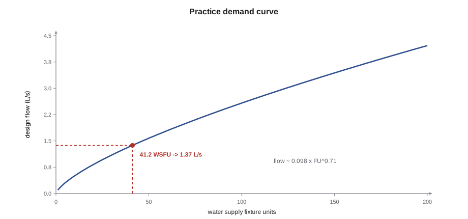
A demand curve converts fixture units into a probable peak flow. It rises steeply at first and then flattens, because the more fixtures a system has, the less likely it is that they are all used at once. Codes give the curve as a table. In this course, a fitted practice curve stands in for it: flow in litres per second is about 0.098 times the fixture units raised to the power 0.71.
Worked problem
Design flow for the main
Convert the main's load of 41.2 fixture units into a design flow.
Show solution
- \[Q = 0.098 \times 41.2^{0.71}\]
- \[41.2^{0.71} = e^{0.71 \ln 41.2} = e^{0.71 \times 3.718} = e^{2.640} \approx 14.0\]
- \[Q \approx 0.098 \times 14.0 \approx 1.37\ \text{L/s}\]
Answer: The design flow is about 1.37 L/s. On the exam, the curve comes as a table, and the calculator is not needed for this step; the logarithm here is only to show where the number comes from.
Two cautions apply. First, systems with flushometer valves use a different, higher curve at small loads, because a flushometer draws a large flow briefly. Second, continuous demands such as a hose bibb used for irrigation or a process load are added to the curve flow, not converted to fixture units, because they do not follow the probability that the curve assumes.
Step 3: the pressure budget
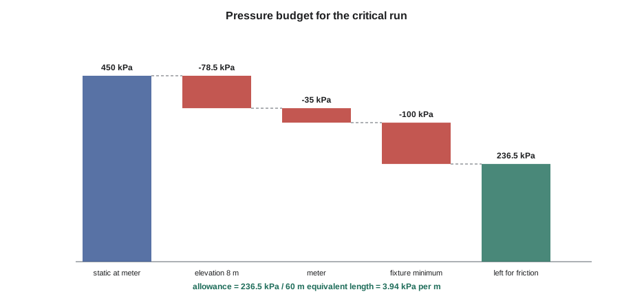
The pressure budget starts at the lowest pressure the supply will deliver, which the water utility can provide, and subtracts every loss except friction in the pipe. What is left is what the pipe is allowed to lose. Lifting water costs about 9.81 kPa for every metre of height. Meters, backflow preventers, strainers and water treatment equipment each cost a pressure drop given by the manufacturer. The critical fixture, the one with the least pressure to spare, usually the highest and farthest, needs a minimum flowing pressure, such as about 55 kPa for a flush tank water closet or more for a flushometer or a pressure-balancing shower valve.
Worked problem
Allowable friction loss
The utility guarantees a minimum static pressure of 450 kPa at the meter. The highest fixture is 8 m above the meter. The meter loses 35 kPa at the design flow. The critical fixture needs 100 kPa. The developed length of the critical run is 40 m, and fittings add 50 per cent. What friction loss per metre is allowed?
Show solution
- \[\Delta P_{\text{elev}} = 8 \times 9.81 \approx 78.5\ \text{kPa}\]
- \[P_{\text{friction}} = 450 - 78.5 - 35 - 100 = 236.5\ \text{kPa}\]
- \[L_{\text{eq}} = 40 \times 1.5 = 60\ \text{m}\]
- \[\frac{236.5}{60} \approx 3.94\ \text{kPa/m}\]
Answer: The pipe may lose up to about 3.94 kPa per metre of equivalent length on the critical run.
The fittings allowance is a shortcut. A detailed method adds the equivalent length of each fitting and valve from a table, but a percentage of the developed length is common in practice and on exams. When a question gives an equivalent length, use it; when it gives a percentage, apply it to the developed length; when it gives neither, read the question again, because it usually gives one.
Steps 4 and 5: friction loss and size
Friction loss in water pipes is usually found from a chart or table based on the Hazen-Williams equation, which relates flow, pipe diameter and a roughness coefficient C. New copper and plastic pipe have C values of about 130 to 150; older steel pipe has much lower values, which is one reason old galvanized systems lose pressure. On the exam, the chart or table is given. Here the equation shows how the numbers behave: friction loss rises with the flow to the power 1.85 and falls with the diameter to the power 4.87. Going up one pipe size roughly halves to thirds the friction loss.
Multiplying the head loss in metres by 9.81 gives kilopascals. For the design flow of 1.37 L/s in copper with C of 130, the friction losses come out at about 12.3 kPa/m in 19 mm pipe, 3.3 kPa/m in 25 mm, 1.2 kPa/m in 32 mm and 0.5 kPa/m in 38 mm. Against the allowance of 3.94 kPa/m, 25 mm is the smallest size that passes on friction.
Step 6: velocity
Fast water is noisy, erodes copper, especially at elbows and on hot water lines, and makes water hammer worse. Many designers and some codes limit velocity, commonly to about 2.4 m/s for cold water and about 1.5 m/s for recirculated hot water. Velocity is the flow divided by the internal area of the pipe.
Worked problem
The velocity check
Check the 25 mm pipe, internal diameter 26.0 mm, at 1.37 L/s, and then the 32 mm pipe, internal diameter 32.1 mm. The limit is 2.4 m/s.
Show solution
- \[A_{25} = \frac{\pi \times 0.0260^2}{4} \approx 5.31 \times 10^{-4}\ \text{m}^2 \to v = \frac{0.00137}{5.31 \times 10^{-4}} \approx 2.59\ \text{m/s}\]
- \[2.59 > 2.4 \to \text{too fast}\]
- \[A_{32} = \frac{\pi \times 0.0321^2}{4} \approx 8.09 \times 10^{-4}\ \text{m}^2 \to v \approx 1.70\ \text{m/s}\]
Answer: The 25 mm pipe passes on friction but fails on velocity. The main is 32 mm. This is the trap in many exam questions: a candidate who stops after the friction check picks 25 mm, which is one of the options.
A water supply sizing calculator
Maya's calculator runs all six steps. It reads a fixture list, applies the practice demand curve, builds the pressure budget, and checks each copper size for both friction and velocity. It prints the result for each size, so that she could see which check governed.
# Water supply main sizing: demand, pressure budget, friction and velocity
import math
fixtures = {"bathroom group": 3.6, "kitchen sink": 1.4, "dishwasher": 1.4, "clothes washer": 1.4}
apartments, cafe = 4, 10.0
wsfu = apartments * sum(fixtures.values()) + cafe
Q = 0.098 * wsfu ** 0.71                    # L/s, practice demand curve
static, rise, meter, fixture_min = 450, 8, 35, 100   # kPa, m, kPa, kPa
length, fittings = 40, 0.5                   # m developed length, 50 % allowance
avail = static - rise * 9.81 - meter - fixture_min
allow = avail / (length * (1 + fittings))    # kPa per m
print(f"Load {wsfu:.1f} WSFU -> design flow {Q:.2f} L/s")
print(f"Pressure for friction {avail:.1f} kPa, allowance {allow:.2f} kPa/m")
C, vmax = 130, 2.4
for name, d_mm in (("19 mm", 19.9), ("25 mm", 26.0), ("32 mm", 32.1), ("38 mm", 38.2)):
    d = d_mm / 1000
    hf = 10.67 * (Q / 1000) ** 1.852 / (C ** 1.852 * d ** 4.87) * 9.81   # kPa/m
    v = (Q / 1000) / (math.pi * d ** 2 / 4)
    ok = "PASS" if hf <= allow and v <= vmax else ("fails friction" if hf > allow else "fails velocity")
print(f"{name}: friction {hf:6.2f} kPa/m, velocity {v:4.2f} m/s {ok}")Load 41.2 WSFU -> design flow 1.37 L/s Pressure for friction 236.5 kPa, allowance 3.94 kPa/m 19 mm: friction 12.26 kPa/m, velocity 4.42 m/s fails friction 25 mm: friction 3.34 kPa/m, velocity 2.59 m/s fails velocity 32 mm: friction 1.19 kPa/m, velocity 1.70 m/s PASS 38 mm: friction 0.51 kPa/m, velocity 1.20 m/s PASS
Try a lower static pressure of 380 kPa. The friction allowance falls, and the governing check can switch from velocity to friction. Questions that change the supply pressure are testing exactly this.
Pressure that is too high
The pressure budget has a top as well as a bottom. When the static pressure at a fixture exceeds the code maximum, commonly about 550 kPa, a pressure-reducing valve is required. In tall buildings, the low floors see the full pressure plus the height of water above, so systems are split into pressure zones, as Maya saw at Kingsway Tower in PLB-330. A question that gives a high street pressure and asks what is required is usually testing the PRV rule, and one of the wrong options will be a larger pipe.
A pressure-reducing valve also adds a pressure drop of its own when water flows, and the downstream setting becomes the new static pressure for the budget. The budget then starts at the PRV setting minus the PRV's falloff at the design flow, not at the street pressure. An exam problem that puts a PRV upstream of the meter or the critical run often hides this step.
Hot water and recirculation
Hot water piping is sized the same way, using the hot column for fixture units, but with two additions. The water heater and any mixing valve add pressure drops to the budget. And in larger buildings, hot water lines are recirculated so that hot water arrives quickly at fixtures, which means the return line is sized for the circulation flow, which is set by the heat lost from the piping, not by fixture demand. The velocity limit for recirculated hot water is lower, because hot water erodes copper faster.
A quick check that comes up in practice questions: a recirculating loop loses 3 kW of heat from its piping, and the designer allows a temperature drop of 5 degrees Celsius around the loop. The circulation flow is the heat loss divided by the product of water's specific heat and the temperature drop, about 0.14 L/s. That flow, not fixture demand, sizes the return line.
Common mistakes
MistakeAdding cold and hot values to get the total.
InsteadUse the total column; it is less than the sum because taps are not fully open together.
MistakeConverting a continuous demand to fixture units.
InsteadAdd continuous flows directly to the curve flow.
MistakeForgetting the elevation loss or using the wrong factor.
InsteadSubtract about 9.81 kPa per metre of height.
MistakeStopping after the friction check.
InsteadAlways check velocity; it often governs at moderate pressures.
MistakeStarting the budget at street pressure when a PRV is installed.
InsteadStart at the PRV setting less its falloff at the design flow.
Summary and key terms
- Water supply sizing combines fixture units, a demand curve, a pressure budget, friction loss and velocity.
- Use cold, hot or total fixture unit columns according to what the pipe serves.
- The demand curve turns fixture units into a probable flow; continuous demands are added on top.
- The pressure budget subtracts elevation, device losses and the fixture minimum from the minimum static pressure.
- Friction loss rises steeply with flow and falls steeply with diameter; the allowance is the available pressure divided by equivalent length.
- Check velocity last; high pressure needs a PRV, and the budget then starts at its setting.
- Water supply fixture unit
- A number representing a fixture's water demand, used with a demand curve.
- Demand curve
- A relationship between fixture units and probable peak flow.
- Pressure budget
- The accounting of static pressure against elevation, device, fixture and friction losses.
- Equivalent length
- Developed length plus an allowance for the friction of fittings and valves.
- Hazen-Williams C
- A roughness coefficient; higher values mean smoother pipe and less friction.
Practice problems
Work each problem on paper first, then reveal the answer to check.
What is the total WSFU of two bathroom groups and two kitchen sinks?
Show answer
2 × 3.6 + 2 × 1.4 = 10.0.
How much pressure is lost lifting water 12 m?
Show answer
About 118 kPa.
Static 400 kPa, 6 m rise, meter 30 kPa, fixture 100 kPa. What is left for friction?
Show answer
400 − 58.9 − 30 − 100, about 211 kPa.
Which check governs when the friction allowance is generous?
Show answer
Usually velocity.
A street pressure of 620 kPa serves a house. What is required?
Show answer
A pressure-reducing valve, because the static pressure exceeds about 550 kPa.
Lesson quiz · 5 questions
Score 60% or more to complete this lesson.
Create a free account to save your progress, take quizzes and earn a certificate.