
PET-360 · Lesson 11 of 12 · 19 min
Injection, falloff and step-rate tests
Produced water from the Tamarack battery goes to the Tamarack 08-31 disposal well, which injects into the Nisku, a carbonate far below the producing zone. The disposal approval sets a maximum injection pressure, and the company has asked to raise its injection rate as water cuts climb. Before the regulator will consider it, Prairie Crest needs two tests: a falloff, to show how the Nisku is taking water and whether the well is damaged, and a step-rate test, to find the pressure at which the rock would start to fracture. Ethan is asked to design and analyse both.
This lesson covers tests on injection wells: injectivity tests, falloff tests and their analysis with the methods of earlier lessons, the complications from the injected fluid bank and thermal effects, and the step-rate test used to find formation parting pressure. Injection wells are tested for the same reasons as producers, and also because their operating limits are regulated to keep injected fluids in the intended zone.
Injection is drawdown in reverse
An injection well is a producer with a negative rate. During injection at a constant rate, the bottomhole pressure rises above the reservoir pressure; this is an injectivity test, the injection equivalent of a drawdown. When injection stops, the pressure falls back toward the reservoir pressure; this is a falloff test, the equivalent of a buildup. Every equation from lessons 2 to 7 applies with q negative, so the semilog slope, the derivative, the skin and the boundary signatures all carry over. A Horner plot of a falloff shows pressure falling as the Horner time ratio decreases, and its straight line extrapolates to p*, the reservoir pressure in an infinite-acting system.
Falloff tests are popular for the same reason buildups are: the rate is zero and well controlled. They are cheap, because injection simply stops for a few days, and in disposal wells they can be repeated every year or two to watch for changes in injectivity. A rising skin over successive falloffs often means plugging by solids, oil, bacteria or scale in the injected water, and indicates that the water treatment or filtering needs attention.
Analysing a falloff
The analysis follows the buildup procedure. The derivative plot identifies wellbore storage, radial flow and any boundary effects; the semilog slope gives kh; the skin follows from the injection pressure at shut-in and the pressure on the straight line at one hour.
The sign of the pressure difference is reversed from a buildup because the pressure is now falling. As before, the metric form uses 5.10 in place of 3.23. The viscosity and compressibility to use are those of the fluid around the well during the radial-flow period, which raises the main complication of injection testing.
# Disposal well: a falloff test analysed like a buildup, and a step-rate test for the fracture pressure
import math
SI = True
def E1(x):
    g, total, term = 0.5772156649, 0.0, 1.0
    for n in range(1, 60):
        term *= -x / n
        total += -term / n
    return -g - math.log(x) + total
if SI:   # metric units
    q, B, mu, h, phi, ct, rw, k, s, p0 = 400.0, 1.0, 0.45, 15.0, 0.10, 6.0e-7, 0.089, 120.0, -1.0, 11800.0
    c_m, c_pD, c_tD, pu = 2149.3, 1866.6, 3.553e-6, "kPa"
    steps = [(100, 12350), (200, 12900), (300, 13450), (400, 14000), (500, 14550), (600, 15000), (700, 15300), (800, 15600)]
    ru = "m3/d"
else:
    q, B, mu, h, phi, ct, rw, k, s, p0 = 15000.0, 1.0, 0.50, 80.0, 0.22, 6.0e-6, 0.35, 400.0, 1.0, 2250.0
    c_m, c_pD, c_tD, pu = 162.6, 141.2, 2.637e-4, "psi"
    steps = [(3000, 2330), (6000, 2405), (9000, 2480), (12000, 2555), (15000, 2630), (18000, 2690), (21000, 2720), (24000, 2750)]
    ru = "bbl/d"
tp = 720.0                                           # 30 days of injection before the shut-in
A = c_pD * q * B * mu / (k * h)
pD = lambda t: 0.5 * E1(1 / (4 * c_tD * k * t / (phi * mu * ct * rw ** 2))) + s
p_inj = p0 + A * pD(tp)                              # injection raises pressure (the sign is reversed)
def pfall(dt): return p0 + A * (pD(tp + dt) - pD(dt))
rows = [((tp + dt) / dt, pfall(dt)) for dt in (2, 4, 8, 16, 24, 48)]
pts = [(math.log10(ht), p) for ht, p in rows]
n = len(pts); sx = sum(x for x, _ in pts); sy = sum(y for _, y in pts)
sxx = sum(x * x for x, _ in pts); sxy = sum(x * y for x, y in pts)
m = (n * sxy - sx * sy) / (n * sxx - sx * sx); b0 = (sy - m * sx) / n
k_est = c_m * q * B * mu / (m * h)
p1h = b0 + m * math.log10(tp + 1)
c_log = -5.10 if SI else -3.23
s_est = 1.1513 * ((p_inj - p1h) / m - math.log10(k_est / (phi * mu * ct * rw ** 2)) - c_log + math.log10((tp + 1) / tp))
print(f"injection pressure at shut-in {p_inj:.0f} {pu}; falloff Horner slope {m:.1f} {pu}/cycle")
print(f"k = {k_est:.0f} mD, skin = {s_est:.2f}, extrapolated pressure {b0:.0f} {pu}")
# step-rate test: two straight lines, one before and one after the formation parts
lo = steps[:5]; hi = steps[5:]
def line(p):
    xs = [a for a, _ in p]; ys = [b for _, b in p]; mx = sum(xs) / len(xs); my = sum(ys) / len(ys)
    sl = sum((x - mx) * (y - my) for x, y in zip(xs, ys)) / sum((x - mx) ** 2 for x in xs); return sl, my - sl * mx
(s1, i1), (s2, i2) = line(lo), line(hi)
q_break = (i2 - i1) / (s1 - s2); p_break = i1 + s1 * q_break
print(f"step-rate break at about {q_break:.0f} {ru} and {p_break:.0f} {pu} (bottomhole)")
print(f"keep the permit's maximum injection pressure below this, with a margin")injection pressure at shut-in 13657 kPa; falloff Horner slope 214.9 kPa/cycle k = 120 mD, skin = -1.00, extrapolated pressure 11800 kPa step-rate break at about 560 m3/d and 14880 kPa (bottomhole) keep the permit's maximum injection pressure below this, with a margin
The synthetic falloff on the Tamarack 08-31 disposal well gives a Horner slope of 215 kPa per cycle, a permeability of 120 mD and a skin of −1, the slightly negative skin of a well that was acidized when completed. The extrapolated pressure is 11,800 kPa, the Nisku pressure. The injection pressure just before shut-in was 13,657 kPa, comfortably below the fracture pressure found later in the step-rate test.
Fluid banks and composite behaviour
When water is injected into a zone that already contains water, as in most disposal wells, the fluid properties are uniform and the analysis is straightforward. When water is injected into an oil reservoir, as in waterflooding, a bank of injected water surrounds the well, with oil beyond it. The two regions have different mobilities and compressibilities, and the falloff shows radial composite behaviour (lesson 8): an early plateau reflecting the water bank and a later one reflecting the oil zone. The distance to the front can be estimated from the transition time and compared with a material-balance estimate from the injected volume.
Temperature adds a second effect. Injected water is often much colder than the reservoir. Cooling contracts the rock near the well and lowers the stress that holds it closed, which can make fractures form at lower pressure than in the virgin formation; it also raises water viscosity near the well, increasing the apparent skin. A long-term injector may therefore have a cooled zone tens of metres across, and both falloff and step-rate interpretations should consider it.
Step-rate tests
A step-rate test increases the injection rate in a series of equal steps, each held for the same time, typically 30 minutes to an hour in permeable rock, while recording the bottomhole pressure at the end of each step. At low rates, the water enters the rock matrix, and pressure rises in proportion to rate, giving a straight line on a Cartesian plot of pressure against rate. Once the pressure reaches the formation parting pressure, a fracture opens, the effective flow area increases, and further increases in rate need much smaller increases in pressure. The plot breaks to a flatter line. The intersection of the two lines is the parting pressure and the corresponding rate.
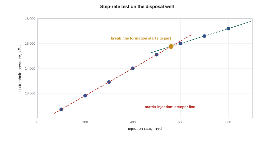
For the Tamarack 08-31 disposal well, the break comes at about 560 m³/d and a bottomhole pressure of 14,880 kPa. The current injection pressure of 13,657 kPa at 400 m³/d is well below it, so there is room for a higher rate. The permit's maximum wellhead pressure will be set from the parting pressure less a margin, after subtracting the hydrostatic head of the water column and adding the friction in the tubing at the higher rate.
Good step-rate design needs equal step durations, so that each point reflects the same transient time; at least three steps below and three above the expected break, so that both lines are well defined; accurate rate control, preferably with a downhole gauge to avoid friction corrections; and a final step not far above the break, so that the fracture does not grow far out of the zone. Some operators follow the steps with a short falloff, in which the closure of the fracture shows as a change in the falloff derivative, giving an independent estimate of the closure stress.
Why injection limits are regulated
A fracture that grows out of the injection zone can carry water into overlying formations, including aquifers used for drinking water, or toward faults. Regulators therefore cap injection pressure below the fracture pressure, require mechanical integrity tests showing that the casing and packer contain the fluid, and require periodic testing. Directive 040 and the injection regulations set out what tests are needed and how often; disposal wells in many jurisdictions also have monitoring requirements because high-rate disposal has been linked to induced seismicity in some basins. A well-run falloff and step-rate programme is the evidence that injection is staying where it should.
| Test | Procedure | Main results |
|---|---|---|
| Injectivity test | Inject at constant rate and record rising pressure | kh, skin, injectivity index |
| Falloff test | Stop injection and record falling pressure | kh, skin, p*, fluid-bank distance |
| Step-rate test | Increase rate in equal steps of equal duration | Formation parting pressure and rate |
| Repeated falloffs | Falloff every one or two years | Trend in skin and injectivity |
| Mechanical integrity test | Pressure the annulus and record the pressure over time | Casing and packer containment |
Worked problem
Injectivity index and the effect of skin
The Tamarack 08-31 disposal well injects 400 m³/d with a bottomhole pressure 1,857 kPa above the reservoir pressure. If the skin were reduced from −1 to −3 by a stimulation, how much lower would the pressure need to be at the same rate?
Show solution
- The injectivity index is 400/1,857 ≈ 0.22 m³/d per kPa.
- The skin pressure change is 0.869 m|Δs| = 0.869 × 215 × 2 ≈ 374 kPa.
- The required pressure above reservoir pressure would fall from 1,857 to about 1,480 kPa.
Answer: Lowering the skin creates room below the parting pressure for a higher rate without raising the injection pressure.
Hall plots: monitoring injection between tests
Between formal tests, injection wells can be watched with a simple diagnostic called the Hall plot, after H. N. Hall, who published it in 1963. It plots the cumulative sum of injection pressure multiplied by time against cumulative injected volume. For steady radial injection, the plot is a straight line whose slope is proportional to the total resistance to flow, including the skin. A slope that steepens over time means the well is becoming harder to inject into, usually from plugging; a slope that flattens suggests the well has fractured or that a channel has opened to another zone. Because it needs only routine daily data, the Hall plot is a cheap early warning that tells the engineer when a falloff or a cleanout is due.
Common mistakes
MistakeUsing oil properties for a falloff in a well surrounded by injected water.
InsteadChoose properties for the region seen during radial flow, or use a composite model.
MistakeRunning step-rate steps of unequal duration.
InsteadUse equal durations so each point reflects the same transient time.
MistakeDefining the break with too few steps.
InsteadUse at least three steps below and three above the expected break.
MistakeIgnoring tubing friction when using surface pressures.
InsteadUse a downhole gauge or correct for friction at each rate.
MistakeTreating a rising falloff skin as a reservoir change.
InsteadCheck the water quality and filtration first; plugging is the usual cause.
Summary and key terms
- Injectivity and falloff tests are drawdowns and buildups with a negative rate.
- Falloff analysis gives kh, skin and p*, and repeated falloffs show trends in plugging.
- Injection into oil zones creates a water bank and radial composite behaviour.
- Cold injected water can lower the fracture pressure near the well and raise apparent skin.
- A step-rate test finds formation parting pressure from the break in a pressure-rate plot.
- Regulators cap injection pressure below parting pressure to keep fluids in the intended zone.
- Injectivity test
- A test that records the rising pressure during constant-rate injection.
- Falloff test
- A test that records the falling pressure after injection stops.
- Step-rate test
- A test with injection rate increased in equal steps to find the formation parting pressure.
- Formation parting pressure
- The pressure at which the rock starts to fracture under injection.
- Injectivity index
- Injection rate divided by the pressure above the reservoir pressure.
- Mechanical integrity
- The ability of the casing, tubing and packer to contain injected fluid.
Practice problems
Work each problem on paper first, then reveal the answer to check.
What is a falloff the injection equivalent of?
Show answer
A buildup.
What does a break to a flatter line on a step-rate plot indicate?
Show answer
The formation has started to part.
Why might a falloff show composite behaviour?
Show answer
A bank of injected fluid surrounds the well.
What usually causes a rising skin in a disposal well?
Show answer
Plugging by solids, oil, bacteria or scale.
Lesson quiz · 5 questions
Score 60% or more to complete this lesson.
Create a free account to save your progress, take quizzes and earn a certificate.