
NUC-440 · Lesson 9 of 12 · 19 min
Digital instrumentation and control
Andrea keeps a binder on her shelf that she calls the history lesson: copies of papers on the licensing of the Darlington shutdown system software at the end of the 1980s. “Darlington was one of the first plants anywhere to put both shutdown systems on computers,” she tells Hana. “The regulator was not convinced the software was correct, and start-up was held up while Ontario Hydro and outside experts, including David Parnas, wrote formal specifications, inspected the code against them and tested it. Afterwards the utility and AECL wrote a software engineering standard and redesigned the software to it. Everything the industry now does for safety software traces back to fights like that one.”
This lesson explains why plants are moving from analogue to digital I&C, how digital safety systems are structured, how they fail differently from analogue equipment, what the software lifecycle and standards require, and how designers defend against common cause failures through diversity and defence in depth.
Why digital
Most nuclear plants operating today were designed with analogue electronics and relay logic. Over decades, the analogue equipment has become hard to maintain: parts are obsolete, vendors have left the market, and drift requires frequent calibration. Digital systems offer clear advantages. They do not drift, they can test and diagnose themselves continuously, they can implement complex functions such as variable setpoints accurately, they reduce wiring and cabinet space, they record data for analysis, and they give operators better displays. Most new reactors, including the BWRX-300 and the other small modular designs, are fully digital from the start.
The risks are different, not absent. A digital system fails in ways that are harder to predict and analyse. Its behaviour depends on software, which does not wear out but can contain design errors that remain hidden until a particular combination of inputs and states occurs. Because redundant channels usually run identical software, a single error can affect them all at once, a software common cause failure. Digital systems also communicate over networks, which creates paths for faults to propagate and, as lesson 10 discusses, for cyber threats.
Architecture of a digital safety system
A typical digital protection system has four redundant divisions. In each division, input modules acquire sensor signals and convert them to digital values; a processor compares them with setpoints and produces partial trip signals; these are shared with the other divisions over one-way, qualified data links; and voting processors or hardwired logic combine them to actuate the trip breakers or safety equipment. Each division is separated physically and electrically. Communication between divisions, and from safety to non-safety systems, is restricted to designs that cannot let a fault or a misbehaving system in one place interfere with safety functions elsewhere: one-way broadcast without handshakes, fixed message formats, and isolation devices that block electrical faults.
The software running on these processors is kept as simple and deterministic as possible. It executes a fixed cycle, reading inputs, computing and writing outputs in a repeating loop with a known worst-case time, rather than responding to interrupts. It avoids dynamic memory allocation, recursion and complex operating systems. Some platforms replace software processors with field-programmable gate arrays, whose logic is configured in hardware; these reduce some software failure modes and are attractive for diversity, though the design of the logic still needs the same rigour.
Software lifecycle and standards
Safety software is developed under a defined lifecycle in which each stage produces documents that are verified against the previous stage: system requirements, software requirements, design, code, integration and validation. Independent verification and validation checks each step, usually by a team separate from the developers. In Canada, CSA N290.14 sets out how digital hardware and software are qualified for use in I&C applications, including the use of pre-developed and commercial products, and REGDOC-2.5.2 sets design expectations for I&C. The international standards are widely referenced: IEC 61513 for I&C systems important to safety, IEC 60880 for software performing category A functions such as reactor trip, IEC 62138 for lower categories, and IEC 61226 for classifying functions into categories. The approach classifies each function by safety importance and grades the rigour of development, verification and qualification accordingly.
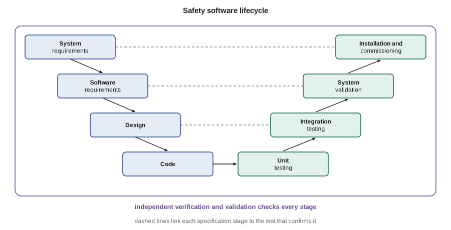
Testing alone cannot show that complex software is free of errors; the number of possible input sequences is far too large. Confidence comes from several sources together: a clear and complete requirements specification, often written in a mathematically precise form such as tables of functions; a simple design; disciplined coding; reviews and inspections that compare code with specification; testing that is driven by the requirements and by structural coverage; and statistical testing with realistic inputs. For the Darlington shutdown system software, the formal specifications were written as tables of functions, and the code was verified against them by systematic inspection and by large numbers of random tests comparing it with an independently written test oracle.
Common cause failure and diversity
Redundant channels protect against random hardware failures, which occur independently. They do not protect against failures that have a common cause: a design error in the software all channels run, a flawed specification, a shared environmental stress, or a maintenance error repeated on every channel. The beta factor model represents this by assuming that a fraction β of each channel's failures are common to all channels.
# Beta-factor common cause failure: why identical redundant channels do not multiply out.
q = 1.0e-3                      # probability one channel fails on demand
for beta in (0.0, 0.01, 0.05, 0.10):
    indep = (1 - beta) * q
    two_of_three_indep = 3 * indep**2 - 2 * indep**3
    total = two_of_three_indep + beta * q
    print(f"beta {beta:4.2f}: 2oo3 system failure {total:.2e} "
          f"(independent part {two_of_three_indep:.1e}, common cause {beta * q:.1e})")
# Two diverse systems (different hardware, software and parameters) in series as backup.
sys_a, sys_b, coupling = 1.0e-5, 1.0e-4, 0.01
print(f"two diverse systems, no coupling: {sys_a * sys_b:.1e}")
print(f"with a small residual coupling: {sys_a * sys_b + coupling * min(sys_a, sys_b):.1e}")beta 0.00: 2oo3 system failure 3.00e-06 (independent part 3.0e-06, common cause 0.0e+00) beta 0.01: 2oo3 system failure 1.29e-05 (independent part 2.9e-06, common cause 1.0e-05) beta 0.05: 2oo3 system failure 5.27e-05 (independent part 2.7e-06, common cause 5.0e-05) beta 0.10: 2oo3 system failure 1.02e-04 (independent part 2.4e-06, common cause 1.0e-04) two diverse systems, no coupling: 1.0e-09 with a small residual coupling: 1.0e-07
The output makes the point vividly. With fully independent channels, two-out-of-three logic gives a system failure probability of 3 × 10⁻⁶. A common cause fraction of only 1 percent raises it to about 1.3 × 10⁻⁵, more than four times worse, and at 10 percent the common cause term dominates completely, so the system is barely better than a single channel. Adding redundant copies of the same design cannot fix this. Diversity can: a second system that differs in hardware, software, design team, measured parameters or physical principle fails for different reasons, and the residual coupling between two diverse systems is much smaller than the coupling between identical channels.
CANDU plants have always relied on diversity: two shutdown systems with different physical means, different trip parameters where practical, different detectors, separate computers and separately developed software. At Darlington the two shutdown system computers were programmed by different teams in different languages. The regulating system is a third, independent line of defence for many events.
Defence in depth in I&C
I&C defence in depth is usually described in echelons. The control systems keep the plant in normal operation. The protection systems trip the reactor when control fails. The engineered safety features actuation systems start safety systems when an accident occurs. And the monitoring and indication systems let the operators understand and manage the plant if all else fails. A diversity and defence-in-depth analysis assumes a common cause failure disables each echelon in turn, and shows that the remaining echelons, or operator actions supported by independent displays, can still cope with each analysed event, sometimes with relaxed acceptance criteria because the combination is beyond the design basis.
Modernization in practice
Canadian plants have modernized I&C in stages during refurbishment. The Darlington refurbishment, completed in 2026, replaced and upgraded parts of the station's control computers and many field instruments while keeping the fundamental two-shutdown-system architecture. Licensees must show the CNSC, through the licensing basis and the safety report, that the new equipment meets REGDOC-2.5.2, CSA N290.14 and the related N290-series standards, and that it does not invalidate the safety analysis. The BWRX-300 at Darlington, licensed for construction in 2025, uses a fully digital architecture with separate safety and non-safety platforms and diverse protection.
Qualifying pre-developed products
Few plants develop safety software from scratch today. Vendors supply qualified platforms, such as programmable logic systems with libraries of function blocks and qualified operating software, on which the plant-specific application is configured. Commercial products not originally designed for nuclear use can also be used if they are dedicated: the user identifies the critical characteristics that the product must have to perform its safety function, then verifies those characteristics through inspection, testing, surveys of the supplier's processes and analysis of operating history. Smart transmitters and digital relays, which contain embedded software, increasingly require this treatment, and the standards provide methods for doing it in a graded way.
Qualification also covers the hardware environment. Digital equipment must withstand electromagnetic interference from radios, welding and switching, so it is tested to electromagnetic compatibility standards and installed with appropriate grounding and shielding. It must survive the seismic motion assumed for its location, with cabinets tested on shake tables. And it must tolerate the temperatures and humidity in its room, including after the loss of ventilation, without the subtle failures that heat can cause in electronics.
Failure modes and self-testing
Analogue failures are mostly obvious: a reading goes to the top or bottom of scale, or drifts. Digital failures can be subtle. A processor may stop updating its outputs while they remain at their last values, or a communication link may deliver stale data. Digital safety systems therefore include watchdog timers that detect a stopped processor and force its outputs to a safe state, continuous self-diagnostics of memory and inputs, and data integrity checks on messages. When designed well, these features make digital systems more reliable than analogue ones, because many faults are detected the moment they occur rather than at the next periodic test. But self-testing software is itself software, and the design must ensure it cannot interfere with the safety function.
Change control
Digital systems are easy to change, which is both a strength and a risk. Every change to safety software or configuration, however small, is controlled: the change is specified, its effect on the safety analysis is assessed, the modified software goes through the lifecycle activities in proportion to the change, the installed version is verified against the approved version, and records are kept. Configuration management ensures that the software running in each channel is exactly the approved version. Andrea tells Hana that the hardest part of digital I&C is not the first installation but keeping control of the system over the decades that follow.
Hana asks whether digital technology has made plants safer. Andrea's answer is careful. Experience worldwide shows that well-designed digital systems have fewer failures, fewer spurious trips and better diagnostics than the analogue equipment they replaced, and that many of the problems encountered were in requirements and in integration with the rest of the plant rather than in code. The plants that have done best kept the architecture simple, invested in clear requirements and verification, maintained diversity and treated the regulator's review as part of the design rather than an obstacle to it.
Small modular reactors add a further twist. Their designers want standardized digital platforms that can be licensed once and deployed many times, with the same software in every unit. That makes the software common cause question bigger, not smaller, because a design error would be shared by every plant in the fleet, and it makes the quality of the original verification and the long-term configuration control all the more important. It also creates an opportunity: a single, well-documented safety case for the platform, reviewed in depth and maintained by the vendor and the operators together, can support many plants with less repeated effort than a different system at every site.
Common mistakes
MistakeSoftware does not fail because it does not wear out.
InsteadIt does not wear out, but design errors can hide until a particular input occurs, and identical copies fail together.
MistakeMore identical channels solve common cause failure.
InsteadOnly diversity reduces common cause failure.
MistakeTesting can prove safety software correct.
InsteadConfidence needs precise requirements, simple design, inspection and testing together.
Summary and key terms
- Digital I&C avoids drift and obsolescence and adds self-testing, but brings software and network risks.
- Safety software is simple, deterministic and developed under a verified lifecycle.
- CSA N290.14, REGDOC-2.5.2 and the IEC standards set qualification and lifecycle requirements.
- Common cause failure limits the benefit of redundancy; the beta factor model quantifies it.
- Diversity and echelons of defence in depth protect against software common cause failure.
- Software common cause failure
- A design error that affects redundant channels running the same software.
- Beta factor
- The fraction of a channel’s failures assumed common to all channels.
- Independent verification and validation
- Checking of each lifecycle stage by a separate team.
- Deterministic cycle
- A fixed loop of input, compute and output with known timing.
- Field-programmable gate array
- A chip whose logic is configured in hardware rather than run as software.
- Diversity
- Differences in design, equipment or principle that avoid shared failures.
Practice problems
Work each problem on paper first, then reveal the answer to check.
Why does a deterministic cycle suit safety software?
Show answer
Its timing is known and it does not depend on unpredictable interrupts.
With β = 0.05 and q = 10⁻³, what is the common cause contribution?
Show answer
5 × 10⁻⁵.
Name two ways of achieving diversity.
Show answer
Different hardware or software platforms; different measured parameters; different physical principles.
What does a diversity and defence-in-depth analysis assume?
Show answer
That a common cause failure disables one echelon, then checks the rest cope.
Why were the Darlington shutdown system programs written by different teams?
Show answer
To make software errors unlikely to be shared.
Lesson quiz · 5 questions
Score 60% or more to complete this lesson.
Create a free account to save your progress, take quizzes and earn a certificate.