
NUC-440 · Lesson 5 of 12 · 20 min
Pressure and level control
Marcel Thibodeau spent fifteen years as an authorized nuclear operator at Darlington before he moved into training, and he still remembers his first boiler level transient. “A feedwater pump tripped and the standby pump did not pick up fast enough,” he tells Hana. “Boiler levels dropped, then the setback cut power and the levels recovered, and I realized I had been holding my breath for a minute. Reactor power is what the public thinks about. Pressures and levels are what the operators watch all day.”
This lesson covers the control of primary system pressure and inventory with a pressurizer, the control of steam generator, or boiler, water level, and the special difficulties of these loops: two-phase physics, shrink and swell, and the interaction between the primary and secondary sides. It closes with the relief and safety valves that protect against pressures the controllers cannot hold.
Why pressure must be controlled
In a pressurized water reactor and in a CANDU heat transport system, the coolant is kept as a subcooled or nearly subcooled liquid by a pressure well above the saturation pressure at its temperature. If pressure falls, the coolant boils in the hottest channels, which reduces heat transfer margin and, in a CANDU core, adds positive void reactivity. If pressure rises, it challenges the strength of the pressure boundary and eventually lifts relief valves. Pressure must therefore be held in a narrow band despite changes in coolant volume as temperatures change with power.
In a Darlington unit the heat transport system operates at a reactor outlet header pressure of about 9.9 MPa, with outlet temperatures near 310 °C. Pressure is controlled by a pressurizer, a vessel partly filled with steam, connected to the heat transport system. Electric heaters in the pressurizer boil water to raise pressure; steam bleed valves relieve steam to the degasser condenser to lower it. At low power, or when the pressurizer is isolated, pressure can also be controlled by feed and bleed, adjusting the flow of water into and out of the system. Older CANDU designs used feed and bleed as the main method.
How a pressurizer works
Because the steam and water in the pressurizer are both at saturation, the pressure is fixed by the temperature of the water. When the primary coolant heats up and expands, water flows into the pressurizer through the surge line, an insurge. The steam space is compressed, pressure rises, and some steam condenses. When the coolant cools and contracts, water flows out, an outsurge, and the falling pressure flashes some of the pressurizer water to steam. The pressurizer is thus a large, two-phase cushion whose pressure changes much less than it would in a solid, water-filled system.
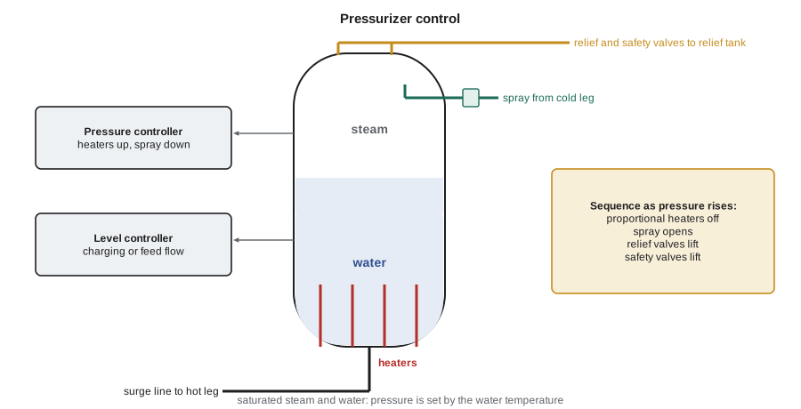
Pressurizer pressure control works in a sequence as error grows. A proportional heater group is modulated continuously around the setpoint, covering the small, steady heat losses. On low pressure, backup heater banks switch fully on. On high pressure, the heaters switch off and steam bleed valves open to the degasser condenser. Beyond the controllers' range, liquid relief valves on the heat transport system protect against overpressure, and the shutdown systems trip the reactor on high heat transport pressure.
# Pressurizer pressure control during an insurge: proportional heaters, spray and a relief setpoint.
P_sp = 15.51           # MPa setpoint
P = P_sp; dt = 0.5
def insurge(t): return 22.0 if 60 <= t < 180 else 0.0   # kg/s of hotter-than-usual surge (illustrative)
log = []
peak = P
for k in range(int(600 / dt)):
    t = k * dt
    err = P - P_sp
    heaters = max(0.0, min(1.0, 0.5 - err / 0.2))             # proportional group, 0..1
    spray = max(0.0, min(1.0, (err - 0.10) / 0.25))           # opens above +0.10 MPa
    porv = 1.0 if P > 16.2 else 0.0
    dP = (0.0012 * insurge(t) + 0.004 * (heaters - 0.5) - 0.030 * spray - 0.10 * porv)
    P += dP * dt
    peak = max(peak, P)
    if k % int(60 / dt) == 0: log.append((t, P, heaters, spray))
print(f"{'t (s)':>6s}{'P (MPa)':>9s}{'heaters':>9s}{'spray':>7s}")
for t, p, h, s in log: print(f"{t:6.0f}{p:9.3f}{h:9.2f}{s:7.2f}")
print(f"peak pressure {peak:.3f} MPa; relief valve {'lifted' if peak > 16.2 else 'not needed'}")
# Steam generator level: why a single-element (level only) controller misreads a load increase.
print("load step +10%: swell raises indicated level first, so level-only control would cut feed;")
print("three-element control adds steam flow minus feed flow so feed rises with the load.") t (s) P (MPa) heaters spray
0 15.510 0.50 0.00
60 15.523 0.50 0.00
120 15.813 0.00 0.81
180 15.800 0.00 0.81
240 15.555 0.27 0.00
300 15.523 0.43 0.00
360 15.514 0.48 0.00
420 15.511 0.49 0.00
480 15.510 0.50 0.00
540 15.510 0.50 0.00
peak pressure 15.813 MPa; relief valve not needed
load step +10%: swell raises indicated level first, so level-only control would cut feed;
three-element control adds steam flow minus feed flow so feed rises with the load.In the simulation the insurge raises pressure by about 0.3 MPa. Within a minute the heaters have switched off and the spray has opened fully, and pressure peaks at 15.81 MPa, well below the relief setpoint. When the surge ends, spray closes and the heaters return to their normal level as pressure settles back to the setpoint. A larger insurge, such as after a turbine trip without steam dumps, would overwhelm the spray, and the relief valve would lift. Designers size the pressurizer volume, heater capacity and spray flow so that the normal operating transients stay within the control range and the analysed upsets stay within the relief capacity.
Pressurizer level and inventory
The level in the pressurizer measures how much coolant the primary system holds. Since coolant density falls as temperature rises, the same mass occupies more volume at power than at zero power. If the level setpoint were constant, the inventory control system would have to remove and store large volumes of water every time power changed. Instead the level setpoint is programmed to rise with power, so that the pressurizer absorbs the expansion. The controller keeps the actual level on this program by adjusting the flow of water into the primary system against a roughly constant outflow.
In a CANDU heat transport system the pressurizer level program rises with reactor power, and inventory is controlled by the feed and bleed system, which can add water from the heavy-water storage tank with feed pumps and remove it to the degasser condenser through bleed valves. Because the coolant is heavy water, every litre removed is valuable, and the inventory system is designed to recover it with high efficiency.
Steam generator level
The level in a steam generator, called a boiler in CANDU plants, must stay inside a band. Too low and the tubes are uncovered and the heat sink is lost; too high and water carries over into the steam lines and the turbine. Level control is difficult for two reasons. First, the indicated level in the downcomer depends on the amount of steam in the riser, not just on the amount of water. Second, the level responds to changes in steam flow in the wrong direction at first.
The second effect is called shrink and swell. When the turbine takes more steam, steam pressure falls and the water in the riser flashes, increasing the void fraction. The two-phase mixture swells and the indicated level rises, even though more water is leaving than entering. A level-only controller would read the rise as too much water and cut feed flow, which is the opposite of what the plant needs. A short time later, as the extra steam leaves and the feed deficit takes effect, level falls sharply. A load reduction does the reverse: level shrinks, then rises. The effect is strongest at low power, where the void fraction is most sensitive to pressure, which is why steam generator level control is hardest during start-up and why many trips in light-water plants have historically occurred at low power on steam generator level.
The standard solution is three-element control. The level controller's output is added to a steam flow signal to form the feedwater flow setpoint, and an inner flow controller holds feedwater flow at that setpoint. When steam flow rises, the feed setpoint rises with it at once, regardless of the swell, and the level controller only trims the long-term balance. At very low power, where flow measurements are inaccurate, plants switch to single-element level control with gentler tuning, often using a separate low-flow bypass valve. Modern digital feedwater controllers also schedule gains with power and use the feed pump speed as an additional manipulated variable to hold a good pressure drop across the valves.
Relief and safety valves
Controllers keep pressures and levels in their normal bands; relief and safety valves protect against conditions the controllers cannot handle. A relief valve is designed to open at a set pressure and reclose when pressure falls; a code safety valve is a spring-loaded self-actuated valve sized to protect the pressure boundary in the worst overpressure event. Both must be tested and maintained, and both can fail: the Three Mile Island accident in 1979 began with a pilot-operated relief valve on the pressurizer that stuck open after the reactor tripped, while the control room indication showed only that the valve had been commanded closed. That failure taught the industry that an indication must show what equipment is actually doing, not what it has been told to do, a lesson revisited in lesson 11.
| Variable | Normal control | Backup action | Protection |
|---|---|---|---|
| Heat transport pressure | pressurizer heaters and steam bleed | feed and bleed | liquid relief valves; shutdown system trips on high and low pressure |
| Pressurizer level | feed and bleed on a level program | operator action | alarms; inventory protection |
| Boiler level | three-element feedwater control | setback on high or low level | shutdown system trip on low boiler level |
| Boiler pressure | turbine governor valves (normal mode) | condenser steam discharge valves | main steam safety valves |
Worked problem
Feed setpoint in three-element control
A steam generator is at 80 percent load with steam flow and feed flow both 400 kg/s . Load rises to 90 percent. The level controller output is 0 kg/s at the moment of the step because level briefly swells above setpoint. What is the new feed flow setpoint, and what would a level-only controller do?
Show solution
- Steam flow rises to 400 × 90/80 = 450 kg/s.
- Feed setpoint = steam flow + level controller output = 450 + 0 = 450 kg/s.
- A level-only controller would see the swell as high level and reduce feed.
Answer: The three-element setpoint rises to 450 kg/s at once; the level-only controller would cut feed just when more is needed.
Interactions between loops
Pressure, level and power loops do not act alone. A rise in reactor power heats the coolant, which expands and causes an insurge, raising pressurizer pressure and level. A rise in turbine load lowers steam pressure, which lowers the primary temperature, causes an outsurge and lowers pressurizer pressure. When the controllers for these variables are tuned independently, they can interact, each disturbing the others. Control engineers check interactions on a plant simulator and, where necessary, detune one loop, add decoupling signals, or rely on the slower loop to follow the faster one.
Operators see these interactions as patterns. After a reactor trip, for example, the primary coolant cools and contracts, pressurizer level falls quickly and pressure follows, while steam generator levels shrink sharply as steam pressure rises and voids collapse. Knowing the expected pattern helps the crew distinguish a normal post-trip transient from a leak or a failed instrument, which is a theme of the simulator exercises in lesson 12.
Marcel's advice to Hana is practical. “When you design or tune a level or pressure loop, ask what the operator will see during the worst transient,” he says. “If the controller makes the indication swing so much that the operator cannot tell what is happening, it does not matter how good the response looks on a plot.”
Digital feedwater control has been one of the most common and successful I&C modernizations in North American plants. Replacing analogue controllers with redundant digital ones, with signal validation of the level, steam flow and feed flow inputs and automatic transfer between controllers, has removed a leading cause of unplanned trips. Because feedwater control is a non-safety system, most such upgrades have been made under the plant's own design change process, with the protection systems unchanged and still independent.
Common mistakes
MistakeA rising steam generator level after a load increase means there is too much water.
InsteadIt is swell; more water is leaving than entering.
MistakePressurizer level should be constant at all powers.
InsteadIt is programmed to rise with power to absorb coolant expansion.
MistakeA relief valve indicated closed is closed.
InsteadIndication must show actual valve position, not the command.
Summary and key terms
- Primary pressure is held by a saturated two-phase pressurizer with heaters and spray or steam bleed.
- Pressurizer level is programmed with power so the pressurizer absorbs coolant expansion.
- Steam generator level is disturbed by shrink and swell, which mislead level-only control.
- Three-element control uses steam flow feedforward and an inner feed flow loop.
- Relief and safety valves protect beyond the controllers' range.
- Pressurizer
- A vessel holding saturated steam and water that sets primary pressure.
- Insurge
- Flow of coolant into the pressurizer as the primary system expands.
- Swell
- A temporary rise in indicated level when steam demand rises and voids grow.
- Three-element control
- Feedwater control using level, steam flow and feed flow.
- Level program
- A setpoint that changes with power or temperature.
- Code safety valve
- A self-actuated spring valve that protects a pressure boundary.
Practice problems
Work each problem on paper first, then reveal the answer to check.
Why does pressurizer pressure change less than a solid system would?
Show answer
The saturated steam space acts as a cushion; steam condenses or flashes.
Which device lowers CANDU pressurizer pressure?
Show answer
Steam bleed valves to the degasser condenser.
Why is steam generator level control hardest at low power?
Show answer
Void fraction is most sensitive to pressure, so shrink and swell are largest, and flow signals are inaccurate.
What does the inner loop of three-element control correct?
Show answer
Valve and feed pump pressure disturbances to feed flow.
What lesson about indication came from the Three Mile Island relief valve?
Show answer
Show actual position, not the command.
Lesson quiz · 5 questions
Score 60% or more to complete this lesson.
Create a free account to save your progress, take quizzes and earn a certificate.