
MEC-450 · Lesson 8 of 12 · 20 min
Meshing, convergence and stress singularities
In machine design, Owen found the stress concentration factor at the TP-80 shaft shoulder from a chart: with a fillet radius of 2.5 mm on a 35 mm shaft stepping up to 42 mm, r/d = 0.07 and D/d = 1.2 gave Kt of about 1.7 in bending. The heavier-duty shaft has a shoulder with a different ratio and a relief groove the charts do not cover, so its Kt must come from a finite element model. Before he trusts a number for the new shaft, Farah asks him to show that he can reproduce the old one, and to show how he knows the mesh is fine enough. This lesson is about that second question, the one that separates a credible stress analysis from a pretty picture.
The axisymmetric shoulder model
A shaft shoulder is a body of revolution, but bending is not axisymmetric: the stress varies around the circumference as the cosine of the angle. Most packages handle this with axisymmetric elements that accept nonsymmetric loads expanded in Fourier harmonics, or the analyst uses a three-dimensional model of a slice with symmetry. Owen uses the simplest equivalent that the charts themselves are based on: a model in which the nominal bending stress is applied at the remote ends, so that the ratio of peak to nominal stress is the stress concentration factor. The nominal bending stress in the 35 mm section, from the 216 N·m moment, is \(32M/\pi d^3 = 51.3\) MPa.
Meshing a fillet requires judgement. The stress peak sits on the fillet surface and decays within a fraction of the fillet radius, so elements there must be much smaller than the radius, while elements far away can be large. Owen uses quadratic elements with a local size set at the fillet surface and graded smoothly outward, so neighbouring elements differ in size by no more than a factor of about 1.5. Abrupt size changes create errors of their own. He runs three meshes with local element sizes of 1.0, 0.5 and 0.25 mm, halving the size each time, and reads the largest axial stress on the fillet.
Is it converged? Richardson extrapolation
Lesson 5 showed that for elements in their asymptotic range, the error is proportional to \(h^p\), where p is the order of convergence. With three meshes and a constant refinement ratio r, the order can be estimated from the results themselves, and the error removed by extrapolation. This procedure, named for Lewis Fry Richardson, who introduced it for finite difference calculations in 1910, is the standard way of quantifying discretization error:
where \(f_1, f_2, f_3\) are the coarse, medium and fine results. Patrick Roache proposed reporting the uncertainty in the fine-mesh result as a grid convergence index, \(\text{GCI} = F_s\,|(f_3 - f_2)/f_3|/(r^p - 1)\), with a safety factor \(F_s\) of 1.25 when three meshes are used. The GCI is now widely used in engineering computation and is recommended in verification guides for solid and fluid mechanics.
# Mesh convergence at the TP-80 shaft shoulder: Richardson extrapolation, the GCI, and a singular sharp corner
import math
M, d = 216.0, 0.035                                  # bending moment at the shoulder (N m) and smaller diameter (m)
s_nom = 32 * M / (math.pi * d**3) / 1e6               # nominal bending stress, MPa
print(f"Nominal bending stress at the shoulder: {s_nom:.2f} MPa")
# Peak axial stress at the 2.5 mm fillet from an axisymmetric model, local element size halved each time
h = [1.0, 0.5, 0.25]; s = [82.9, 86.1, 86.9]           # mm and MPa (Owen's three runs)
r = h[0] / h[1]
p = math.log((s[1] - s[0]) / (s[2] - s[1])) / math.log(r)
s_ext = s[2] + (s[2] - s[1]) / (r**p - 1)
gci = 1.25 * abs((s[2] - s[1]) / s[2]) / (r**p - 1)
print(f"Observed order of convergence p = {p:.2f} (theory about 2 for quadratic elements measured in stress)")
print(f"Richardson extrapolated peak stress {s_ext:.2f} MPa, so Kt = {s_ext/s_nom:.2f} (chart value 1.7)")
print(f"Grid convergence index on the finest mesh {100*gci:.2f} percent")
print("Fine-mesh error estimates: " + ", ".join(f"h = {hh} mm: {100*(s_ext-ss)/s_ext:.2f} %" for hh, ss in zip(h, s)))
# The same shoulder modelled with a sharp corner (no fillet): the stress never settles
hs = [1.0, 0.5, 0.25, 0.125]; ss = [98.0, 121.0, 150.0, 186.0]
print("\nSharp corner:  h (mm)   peak (MPa)   growth per halving")
for i, (a, b) in enumerate(zip(hs, ss)):
    g = f"{b/ss[i-1]:.3f}" if i else "  -  "
    print(f"               {a:6.3f}     {b:6.1f}        {g}")
lam = math.log(ss[-1] / ss[-2]) / math.log(2)
print(f"Stress grows roughly as h^-{lam:.2f}: a singularity, not a converging peak")
print(f"Linear elastic theory for a 90 degree re-entrant corner gives a stress exponent of about {1-0.5445:.2f}")
# Simple element quality checks for a quadrilateral: aspect ratio and the largest corner angle
def quality(pts):
    sides = [math.dist(pts[i], pts[(i+1) % 4]) for i in range(4)]
    angs = []
    for i in range(4):
        a, b, c = pts[i-1], pts[i], pts[(i+1) % 4]
        v1 = (a[0]-b[0], a[1]-b[1]); v2 = (c[0]-b[0], c[1]-b[1])
        angs.append(math.degrees(math.acos((v1[0]*v2[0] + v1[1]*v2[1]) / (math.hypot(*v1) * math.hypot(*v2)))))
    return max(sides) / min(sides), max(angs)
for name, q in (("good", [(0, 0), (1, 0), (1, 1), (0, 1)]), ("stretched", [(0, 0), (6, 0), (6, 1), (0, 1)]),
                ("skewed", [(0, 0), (1, 0), (2.2, 1), (1.2, 1)])):
    ar, amax = quality(q)
print(f"{name:10s}: aspect ratio {ar:4.1f}, largest corner angle {amax:5.1f} degrees")Nominal bending stress at the shoulder: 51.32 MPa
Observed order of convergence p = 2.00 (theory about 2 for quadratic elements measured in stress)
Richardson extrapolated peak stress 87.17 MPa, so Kt = 1.70 (chart value 1.7)
Grid convergence index on the finest mesh 0.38 percent
Fine-mesh error estimates: h = 1.0 mm: 4.89 %, h = 0.5 mm: 1.22 %, h = 0.25 mm: 0.31 %
Sharp corner: h (mm) peak (MPa) growth per halving
1.000 98.0 -
0.500 121.0 1.235
0.250 150.0 1.240
0.125 186.0 1.240
Stress grows roughly as h^-0.31: a singularity, not a converging peak
Linear elastic theory for a 90 degree re-entrant corner gives a stress exponent of about 0.46
good : aspect ratio 1.0, largest corner angle 90.0 degrees
stretched : aspect ratio 6.0, largest corner angle 90.0 degrees
skewed : aspect ratio 1.6, largest corner angle 140.2 degrees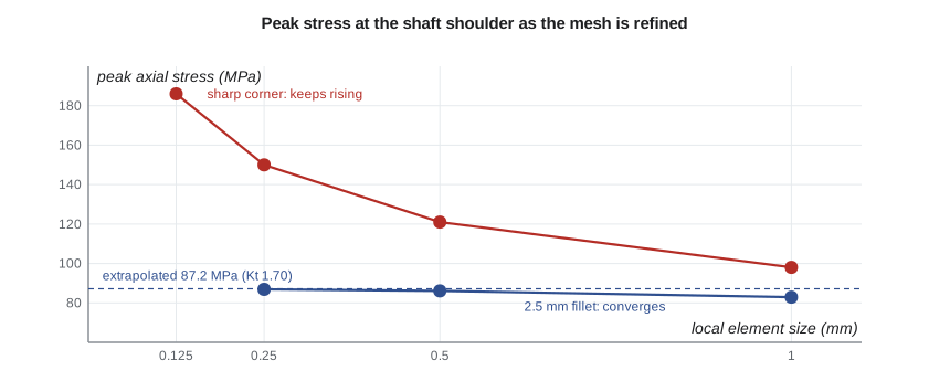
Owen's three results are 82.9, 86.1 and 86.9 MPa. The changes, 3.2 and then 0.8 MPa, fall by a factor of four as h halves, giving an observed order of 2.00, exactly what quadratic elements should show for stress. The extrapolated peak is 87.17 MPa, so Kt = 87.17/51.32 = 1.70, the chart value. The GCI of the finest mesh is 0.38 percent, and the estimated errors of the three meshes are 4.9, 1.2 and 0.3 percent. Owen now knows not only the answer but how good each mesh is: for the heavier-duty shaft, a 0.5 mm local size will give the peak to about one percent, which is adequate for a fatigue calculation whose other inputs are far less certain.
The important point is the order. If the observed order had come out as 0.4 or 5, or if the changes had not shrunk steadily, the meshes would not be in the asymptotic range and the extrapolation would mean nothing. In that case the cure is more refinement, smoother grading or a check for a modelling error, not a report of the finest result.
Stress singularities
Owen then repeats the study with the fillet removed, a perfectly sharp internal corner. The peak stress is 98 MPa with the coarsest mesh and grows by about 24 percent every time the mesh is halved, to 186 MPa at 0.125 mm, with no sign of levelling off. This is a stress singularity. Linear elasticity predicts that at a sharp re-entrant corner the stress is infinite, varying as \(r^{\lambda - 1}\) with distance r from the corner, where λ depends on the corner angle; for a 90 degree corner, the classical analysis by Max Williams gives λ ≈ 0.544, so the stress grows as \(r^{-0.46}\). A finite element mesh reports a finite stress at the corner only because each element averages over its own size, and the reported value grows without limit as the elements shrink.
Singularities appear in many places in practical models: sharp internal corners, the edge of a point load or point support, the tip of a crack, and the edge of a perfectly rigid support or a bonded joint between dissimilar materials. None of them represents real stress. Real corners have some radius, real loads are spread over an area, and real materials yield locally. The correct responses depend on why the stress is wanted. If the corner is a real design feature, model its actual radius, and if the radius is unknown, specify one on the drawing. If the singularity comes from an idealized support or load, read stresses away from it, at a distance of a few element sizes, where Saint-Venant's principle says the details no longer matter. If the corner is a crack, use fracture mechanics, which describes the singular field by a stress intensity factor instead of a stress.
The trap is a model that is not refined. A single mesh of a sharp corner gives a plausible-looking finite stress, and an analyst who does not refine it will never know that the number depends entirely on the element size. A convergence study exposes the problem at once, which is the strongest argument for always doing one at the locations that matter.
Element quality
The program's last part computes two quality measures for three quadrilaterals. The good element has an aspect ratio of 1 and right angles. The stretched element, six times longer than it is wide, has an aspect ratio of 6: acceptable along a shaft where the stress hardly changes axially, poor at the fillet. The skewed element has a reasonable aspect ratio, 1.6, but a corner angle of 140 degrees, close to the limit beyond which accuracy deteriorates. Meshers report statistics of these measures, and most let the user set limits that trigger local remeshing. Owen's rule from Farah is to check the quality of the elements at every location where a result will be reported, not just the average over the model.
Worked problem
How fine is fine enough?
For the heavier-duty shaft, Owen's first two meshes, with 1.0 and 0.5 mm elements at the relief groove, give peaks of 112.4 and 116.8 MPa. Assuming the same order of 2 as before, estimate the converged peak and the error of the 0.5 mm mesh, and decide whether a third mesh is needed.
Show solution
- With p = 2 and r = 2, \(f_{ext} = 116.8 + (116.8 - 112.4)/3 = 118.3\) MPa.
- The 0.5 mm mesh error is about 1.5/118.3 = 1.3 percent.
- But the order of 2 has been assumed, not observed; two meshes cannot confirm it.
- A third mesh at 0.25 mm is needed to verify that the groove's stress is in the asymptotic range and not singular.
Answer: The estimate is about 118 MPa, but Owen runs the third mesh: with only two results, convergence is assumed rather than demonstrated.
Adaptive meshing and error estimates
Many packages estimate the discretization error of each element automatically, most commonly by comparing the raw element stresses with the smoothed nodal stresses, an approach associated with Olgierd Zienkiewicz and Jian Zhu. Some then refine the mesh automatically where the error is largest, repeating until a target is met. These tools are valuable, especially for large models, but they share the limitations of any convergence check: at a singularity, the error estimate stays high however much the mesh is refined, and an adaptive scheme will keep refining a corner whose stress is not real. The analyst still has to understand the geometry well enough to know which peaks are physical.
Common mistakes
MistakeReporting the peak stress from a single mesh.
InsteadRun at least three meshes with a constant refinement ratio at locations that matter.
MistakeExtrapolating when the observed order is erratic.
InsteadRichardson extrapolation requires results in the asymptotic range; refine further first.
MistakeReading stress at a sharp corner, point load or point support.
InsteadThese are singular; model the real radius or read stresses a few elements away.
MistakeGrading element sizes abruptly.
InsteadChange size gradually, by no more than about 1.5 between neighbours, near regions of interest.
MistakeTrusting adaptive refinement to tell physical peaks from singularities.
InsteadDecide from the geometry which peaks are real; refinement keeps chasing singularities.
Summary and key terms
- The nominal bending stress at the TP-80 shoulder is 51.3 MPa; three meshes give 82.9, 86.1 and 86.9 MPa.
- The observed order is 2.00, the extrapolated peak 87.17 MPa and Kt 1.70, matching the chart; the GCI is 0.38 percent.
- Richardson extrapolation and the GCI quantify discretization error, but only in the asymptotic range.
- A sharp corner's stress grows about 24 percent per halving of element size: a singularity with no finite answer.
- Singularities arise at sharp corners, point loads and supports, cracks and rigid edges; model real details or read stresses elsewhere.
- Check element quality where results are reported, and grade mesh sizes smoothly.
- Mesh convergence study
- A series of analyses with refined meshes to show that a result has settled.
- Asymptotic range
- The range of element sizes in which error falls at the theoretical rate.
- Richardson extrapolation
- Estimating the zero-element-size result from a sequence of refined meshes.
- Grid convergence index
- A measure of the discretization uncertainty in a fine-mesh result.
- Observed order
- The order of convergence calculated from the results themselves.
- Stress singularity
- A point where linear elasticity predicts infinite stress, so mesh refinement never converges.
- Re-entrant corner
- An internal corner of a body, a common source of singularities.
- Saint-Venant's principle
- The principle that local details of load application affect stress only nearby.
- Mesh grading
- A gradual change in element size from fine to coarse regions.
- Error estimator
- A calculation that estimates the discretization error of each element.
Practice problems
Work each problem on paper first, then reveal the answer to check.
Three meshes with r = 2 give 50.0, 54.0 and 55.0 MPa. What is the observed order?
Show answer
ln(4/1)/ln 2 = 2.0.
For those results, what is the extrapolated value?
Show answer
55.0 + 1.0/3 = 55.33 MPa.
From the program, what is the estimated error of the 1.0 mm mesh at the fillet?
Show answer
4.89 percent.
The peak stress at a corner rises from 140 to 170 to 210 MPa as the mesh is halved twice. What should you conclude?
Show answer
It is not converging, probably a singularity; model the actual radius or read stress away from the corner.
Why may a point support produce a stress singularity?
Show answer
All the reaction passes through one node, an infinitely small area, so local stress grows without limit as the mesh is refined.
Lesson quiz · 5 questions
Score 60% or more to complete this lesson.
Create a free account to save your progress, take quizzes and earn a certificate.