
MEC-450 · Lesson 3 of 12 · 22 min
Plane trusses and coordinate transformation
The heavier-duty TP-80 has a control box for its vibration and temperature monitoring, and the mining customer wants it mounted on the wall of the pump house beside the unit, clear of hose-down spray. Marco Rossi has sketched a bracket made of steel angles: two horizontal members off the wall, a vertical, two diagonals and a short outer member reaching to the box mounting point, 1.6 m from the wall. The design load, which includes the box, a technician leaning on it and an allowance for impact, is 3 kN at the tip. A welded bracket of angles behaves very nearly as a pin-jointed truss when its members are slender and meet at their centroids, and a truss is the natural next step from the bar: the same element, but now pointing in any direction in a plane.
Bars at an angle
In Lesson 2 the bar lay along the x axis and each node had one degree of freedom. In a plane truss each node can move in both x and y, so it has two degrees of freedom, and each bar has four. The bar still carries only axial force, which depends only on the stretch along its own axis. If the bar makes an angle θ with the global x axis, with direction cosines \(c = \cos\theta\) and \(s = \sin\theta\), then a nodal displacement \((u, v)\) has a component \(cu + sv\) along the bar. The stretch is the difference of those components at the two ends, and the axial force acts along the bar, so its global components are c and s times the force.
Putting these together gives the element stiffness matrix in global coordinates:
This matrix can also be written as \(k = T^{\mathsf{T}} k' T\), where k′ is the bar stiffness in the element's own axis and T is a transformation matrix built from c and s. That form is the one used for every element type in software: matrices are derived in a convenient local coordinate system and transformed to the global system before assembly. The same idea will reappear for beam and frame elements in Lesson 4 and, in more elaborate form, for shells in Lesson 9.
As a check, a horizontal bar has c = 1 and s = 0, and the matrix reduces to the Lesson 2 bar stiffness in the x directions with zeros in the y directions. Those zeros are physically correct: a bar pinned at both ends offers no resistance to a small sideways movement. They also explain a common failure of truss models. A node where all the connected bars are collinear has no stiffness perpendicular to them, so the global matrix is singular. Real structures avoid such mechanisms by triangulation, and finite element models must do the same or add the missing restraint.
The bracket model
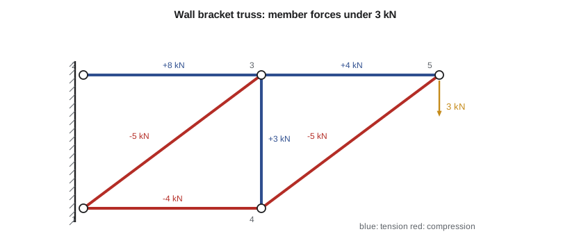
Owen numbers the joints from the wall. Joints 1 and 2 are on the wall, 0.6 m apart vertically, and are pinned. Joints 3 and 4 are 0.8 m out, with 3 at the top and 4 at the bottom, and joint 5 is the tip, 1.6 m out at the height of the top chord. The six members are the bottom chord 1-4, the top chord 2-3, the diagonal 1-3, the vertical 3-4, the outer top member 3-5 and the outer diagonal 4-5. Each angle has an area of 480 mm². With ten degrees of freedom and four of them restrained, the free system is 6 by 6.
# Plane truss: a welded wall bracket of steel angles carrying 3 kN, solved by the direct stiffness method
import math
def solve(A, b):
    n = len(b); A = [r[:] for r in A]; b = b[:]
    for k in range(n):
        p = max(range(k, n), key=lambda i: abs(A[i][k])); A[k], A[p] = A[p], A[k]; b[k], b[p] = b[p], b[k]
        for i in range(k + 1, n):
            f = A[i][k] / A[k][k]
            for j in range(k, n): A[i][j] -= f * A[k][j]
            b[i] -= f * b[k]
    x = [0.0] * n
    for i in range(n - 1, -1, -1): x[i] = (b[i] - sum(A[i][j] * x[j] for j in range(i + 1, n))) / A[i][i]
    return x

nodes = {1: (0.0, 0.0), 2: (0.0, 0.6), 3: (0.8, 0.6), 4: (0.8, 0.0), 5: (1.6, 0.6)}   # m
members = [(1, 4), (2, 3), (1, 3), (3, 4), (3, 5), (4, 5)]
E, A = 200e9, 480e-6                                # steel angle, Pa and m^2
loads = {(5, 'y'): -3000.0}                          # 3 kN down at the tip
fixed = {(1, 'x'), (1, 'y'), (2, 'x'), (2, 'y')}     # both wall joints pinned
dof = {}
for n in nodes:
    dof[(n, 'x')] = len(dof); dof[(n, 'y')] = len(dof)
N = len(dof); K = [[0.0] * N for _ in range(N)]
geo = {}
for i, j in members:
    (xi, yi), (xj, yj) = nodes[i], nodes[j]; Le = math.hypot(xj - xi, yj - yi); c, s = (xj - xi) / Le, (yj - yi) / Le
    geo[(i, j)] = (Le, c, s); k = E * A / Le
    ke = [[c*c, c*s, -c*c, -c*s], [c*s, s*s, -c*s, -s*s], [-c*c, -c*s, c*c, c*s], [-c*s, -s*s, c*s, s*s]]
    idx = [dof[(i, 'x')], dof[(i, 'y')], dof[(j, 'x')], dof[(j, 'y')]]
    for a in range(4):
        for b in range(4): K[idx[a]][idx[b]] += k * ke[a][b]
free = [d for key, d in sorted(dof.items(), key=lambda t: t[1]) if key not in fixed]
F = [0.0] * N
for key, v in loads.items(): F[dof[key]] = v
uf = solve([[K[a][b] for b in free] for a in free], [F[a] for a in free])
u = [0.0] * N
for d, v in zip(free, uf): u[d] = v
print("Joint displacements (mm):")
for n in nodes: print(f"  joint {n}: ux {1e3*u[dof[(n,'x')]]:8.4f}   uy {1e3*u[dof[(n,'y')]]:8.4f}")
print("Member forces (kN, tension positive) and stresses (MPa):")
for i, j in members:
    Le, c, s = geo[(i, j)]
    du = (u[dof[(j,'x')]] - u[dof[(i,'x')]]) * c + (u[dof[(j,'y')]] - u[dof[(i,'y')]]) * s
    Fm = E * A * du / Le
    print(f"  {i}-{j}: L {Le:.3f} m  force {Fm/1e3:7.3f}  stress {Fm/A/1e6:7.2f}")
Rx = sum(sum(K[dof[key]][m] * u[m] for m in range(N)) for key in fixed if key[1] == 'x')
Ry = sum(sum(K[dof[key]][m] * u[m] for m in range(N)) for key in fixed if key[1] == 'y')
print(f"Sum of support reactions: x {Rx:.2f} N, y {Ry:.2f} N (must balance the 3,000 N load)")Joint displacements (mm): joint 1: ux 0.0000 uy 0.0000 joint 2: ux 0.0000 uy 0.0000 joint 3: ux 0.0667 uy -0.1757 joint 4: ux -0.0333 uy -0.1944 joint 5: ux 0.1000 uy -0.4590 Member forces (kN, tension positive) and stresses (MPa): 1-4: L 0.800 m force -4.000 stress -8.33 2-3: L 0.800 m force 8.000 stress 16.67 1-3: L 1.000 m force -5.000 stress -10.42 3-4: L 0.600 m force 3.000 stress 6.25 3-5: L 0.800 m force 4.000 stress 8.33 4-5: L 1.000 m force -5.000 stress -10.42 Sum of support reactions: x -0.00 N, y 3000.00 N (must balance the 3,000 N load)
Checking by the method of joints
Because this truss is statically determinate, every member force can also be found by hand, which makes it an ideal test of the program. Start at joint 5, where only two members meet. The outer diagonal 4-5 rises 0.6 m over 0.8 m, so its length is 1.0 m and its sine is 0.6. Vertical equilibrium at the tip needs \(0.6 F_{45} = 3\) kN pushing up, so the diagonal is in compression with 5 kN. Horizontal equilibrium then needs the outer top member 3-5 to pull the joint toward the wall with 4 kN of tension. At joint 4, the 5 kN compression of the diagonal pushes the joint down and toward the wall with components of 3 kN and 4 kN; the vertical 3-4 must pull up with 3 kN of tension, and the bottom chord must push back with 4 kN of compression. The same reasoning at joint 3 gives the top chord 8 kN of tension and the inner diagonal 5 kN of compression.
The program's results match exactly, and the sum of the support reactions balances the 3 kN load to within rounding, so the model passes both independent checks. Owen keeps the hand calculation in his file as the verification record for the program; when the bracket design later changes, he can rerun the program with confidence that its assembly and transformation are correct.
The joint displacements add information that the method of joints does not give. The tip drops by 0.459 mm and moves 0.100 mm away from the wall. A cantilevered bracket that deflects about half a millimetre under 3 kN is stiff enough for an instrument box; if the box held a vibration sensor that needed a rigid mount, Owen would look instead at the natural frequency, as Lesson 11 does for the baseplate.
Stress, buckling and what the truss model leaves out
The member stresses are low, the highest being 16.7 MPa of tension in the top chord. Stress alone does not settle the design, however, because three members are in compression, and a slender compression member fails by buckling long before its material yields. A linear finite element analysis of a truss, like the one in the program, knows nothing about buckling: it would report the same compressive stress whether the diagonal were a stocky bar or a thin rod. The 1.0 m diagonals carrying 5 kN must be checked separately, by an Euler or design-code column formula using the angle's least radius of gyration, or by a buckling (eigenvalue) analysis in the software. For a typical 50 × 50 × 5 mm angle the buckling load over 1 m is many times 5 kN, so the bracket is comfortably safe, but the check must still be made and recorded.
The truss idealization also assumes pinned joints. Welded joints are rigid, so the real bracket carries some bending in its members, called secondary bending. For slender members meeting at their centroids the secondary stresses are usually small, a common design assumption, but where members are short and stocky or the joints are eccentric, a frame model with beam elements, the subject of Lesson 4, is the better idealization. An experienced analyst often runs both and compares them: if the axial forces agree closely, the truss model was adequate.
Finally, the model says nothing about the wall anchors, which in practice govern many bracket failures. The reactions at joints 1 and 2 give the anchor loads directly: the top chord pulls joint 2 away from the wall with 8 kN, so the top anchor is in tension, while the two compression members push joint 1 into the wall with 8 kN and down with the full 3 kN, so the bottom anchor carries compression and all of the shear. Those numbers go to whoever selects the anchors for the concrete or masonry wall. A finite element model is only part of a design check, and its reactions are often its most useful output.
Worked problem
A heavier box
The customer changes to a larger box with a design load of 4.5 kN at the same point. Without rerunning the program, what are the forces in the top chord and the inner diagonal, and how far does the tip drop?
Show solution
- The model is linear: every force and displacement scales with the load.
- Scale factor 4.5/3 = 1.5.
- Top chord 8 × 1.5 = 12 kN tension; inner diagonal 5 × 1.5 = 7.5 kN compression.
- Tip deflection 0.459 × 1.5 = 0.689 mm.
Answer: Linearity lets results be scaled and superposed, which is one of the great conveniences of linear analysis. It fails as soon as the problem becomes nonlinear through contact, large deflection, yielding or buckling.
Statically indeterminate trusses
Add one more member to the bracket, say a diagonal from joint 2 to joint 4, and the truss becomes statically indeterminate: there are more unknown member forces than independent equilibrium equations, and the method of joints can no longer find them. The stiffness method does not care. It assembles one more element, solves, and the forces distribute according to the members' relative stiffnesses. That is one of the method's main strengths: indeterminate structures, which are hard to analyse by hand, are no harder than determinate ones. It is also a caution: in an indeterminate structure, a member that is made stiffer attracts more load, so changing a section size can change force distribution in a way intuition may not anticipate. The model must be rerun after every change.
Sizes of real truss models
A large transmission tower or a stadium roof truss can have thousands of members, but the matrices remain small by finite element standards, a few tens of thousands of degrees of freedom. The challenges in such models are rarely computational. They are in the loads, such as wind and ice combinations, in the joint details and in buckling, which a design code governs. Software for these structures typically includes code checks, which compare each member against the applicable steel design standard. The analyst's responsibility is to see that the model's idealization matches the structure and that the code checks are the right ones for the jurisdiction.
Common mistakes
MistakeTreating a linear truss analysis as a check against buckling.
InsteadCheck compression members separately with a column formula or a buckling analysis.
MistakeLeaving a joint where all members are collinear.
InsteadTriangulate the structure, or the stiffness matrix will be singular.
MistakeIgnoring support reactions once member forces are found.
InsteadReactions are the anchor and connection loads; report them.
MistakeAssuming secondary bending is always negligible.
InsteadCompare with a frame model when members are stocky or joints are eccentric.
MistakeScaling results linearly after the problem becomes nonlinear.
InsteadSuperposition holds only for linear behaviour: no contact, yielding, buckling or large deflection.
Summary and key terms
- A plane truss element has four degrees of freedom; its stiffness is the bar stiffness transformed with c = cos θ and s = sin θ.
- Software derives elements in local coordinates and transforms them as k = Tᵀk′T.
- The wall bracket gives member forces of +8, +4, +3, −4, −5 and −5 kN, matching the method of joints, with a 0.459 mm tip drop.
- Linear truss analysis does not predict buckling; compression members need a separate check.
- Reactions give the anchor loads, often the most important output of a bracket model.
- The stiffness method handles indeterminate trusses as easily as determinate ones.
- Plane truss
- A structure of pin-jointed bars lying in a plane, carrying only axial forces.
- Direction cosine
- The cosine of the angle between an element axis and a global axis.
- Transformation matrix
- The matrix that converts an element's local degrees of freedom to global ones.
- Method of joints
- A hand method that finds truss member forces from equilibrium at each joint.
- Mechanism
- An arrangement that can move without deforming any member, giving a singular stiffness matrix.
- Secondary bending
- Bending in truss members caused by rigid joints, ignored in the pin-jointed idealization.
- Buckling
- Sudden sideways failure of a slender compression member.
- Superposition
- Adding results of separate load cases, valid only for linear behaviour.
- Code check
- Comparison of member forces with the capacities required by a design standard.
- Reaction
- The force a support applies to a structure.
Practice problems
Work each problem on paper first, then reveal the answer to check.
A truss member at 30° to the x axis has c and s equal to what?
Show answer
c = 0.866, s = 0.5.
For a vertical member, which entries of the global stiffness matrix are nonzero?
Show answer
Only the y-direction terms (s = 1, c = 0).
From the program, what is the stress in the outer diagonal 4-5?
Show answer
−10.42 MPa, compression.
Why is the tip of the bracket displaced away from the wall as well as downward?
Show answer
The top members stretch in tension, so the joints at the top move outward.
A colleague adds a member 2-4. Can the method of joints still find all member forces?
Show answer
No: the truss becomes statically indeterminate, so stiffness (compatibility) is needed.
Lesson quiz · 5 questions
Score 60% or more to complete this lesson.
Create a free account to save your progress, take quizzes and earn a certificate.