
MEC-450 · Lesson 7 of 12 · 22 min
Isoparametric elements and numerical integration
The constant-strain triangle has straight sides and constant strain, and the integral that gives its stiffness can be done by hand. Better elements have strains that vary, sides that may be curved and integrals that cannot be evaluated in closed form for a general shape. The solution adopted by essentially every finite element program, developed in the 1960s, is the isoparametric element: every element is treated as a distorted copy of a simple parent shape, a square or a cube, and its integrals are evaluated numerically by Gauss quadrature at a few points inside the parent. This lesson builds the four-node quadrilateral, the Q4, in that way, explains what the Jacobian and the integration points are, and shows why element shape matters.
The parent element and the mapping
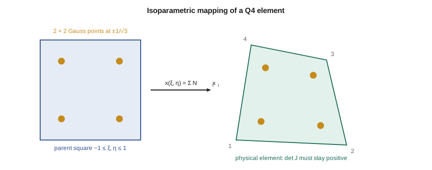
The parent element is a square in natural coordinates ξ and η, each running from −1 to 1. The bilinear shape functions
where \((\xi_i, \eta_i)\) are the parent corner coordinates, equal one at their own corner and zero at the others. The element is called isoparametric because the same functions serve two purposes: they interpolate the displacement from the nodal values, \(u = \sum N_i u_i\), and they map the parent square onto the real element, \(x = \sum N_i x_i\), \(y = \sum N_i y_i\). A square maps to any convex quadrilateral. With eight-node quadratic shape functions, a parent square maps to an element with curved sides, which fits a fillet or bore far better than straight-sided elements.
The Jacobian
Strains need derivatives with respect to x and y, but the shape functions are written in ξ and η. The chain rule connects them through the Jacobian matrix of the mapping:
Its determinant, det J, is the ratio of a small area in the real element to the corresponding area in the parent, so \(dx\,dy = \det J\,d\xi\,d\eta\). For a square element 10 mm on a side, det J is 25 everywhere: the real area of 100 mm² is 25 times the parent's area of 4. For a distorted element, det J varies from point to point. If any part of the element is folded back on itself, as happens when one corner is pushed inward past the line joining its neighbours, det J becomes negative there. The mapping is then not one-to-one, and the stiffness matrix is meaningless. Software checks det J at every integration point and refuses to solve, or reports a distorted element, when it is zero or negative.
Gauss quadrature
The element stiffness becomes an integral over the parent square, \(k = \int_{-1}^{1}\int_{-1}^{1} B^{\mathsf{T}}DB\,t\,\det J\,d\xi\,d\eta\), whose integrand is a ratio of polynomials for a distorted element. It is evaluated numerically. Carl Friedrich Gauss showed that with n carefully placed points and weights, the integral of any polynomial up to degree 2n − 1 over [−1, 1] is exact. One point at the centre, weight 2, integrates linear functions exactly; two points at \(\pm 1/\sqrt{3}\), weight 1, integrate cubics; three points at 0 and \(\pm\sqrt{0.6}\), weights 8/9 and 5/9, integrate fifth-degree polynomials. In two dimensions the rule is applied in each direction, so the Q4 uses a 2 × 2 grid of four points and quadratic elements usually a 3 × 3 grid.
# Isoparametric quadrilaterals and Gauss quadrature: exactness, the Jacobian, and Q4 elements in bending
import math
GP = {1: [(0.0, 2.0)], 2: [(-1/math.sqrt(3), 1.0), (1/math.sqrt(3), 1.0)],
      3: [(-math.sqrt(0.6), 5/9), (0.0, 8/9), (math.sqrt(0.6), 5/9)]}
print("Gauss quadrature of x^k on [-1, 1]:  k   exact     1 point   2 points   3 points")
for k in range(7):
    ex = 0.0 if k % 2 else 2 / (k + 1)
    vals = [sum(w * x**k for x, w in GP[n]) for n in (1, 2, 3)]
    print(f"                                   {k}   {ex:7.4f}   " + "   ".join(f"{v:7.4f}" for v in vals))
def shape(xi, eta):
    N = [(1-xi)*(1-eta)/4, (1+xi)*(1-eta)/4, (1+xi)*(1+eta)/4, (1-xi)*(1+eta)/4]
    dxi = [-(1-eta)/4, (1-eta)/4, (1+eta)/4, -(1+eta)/4]; deta = [-(1-xi)/4, -(1+xi)/4, (1+xi)/4, (1-xi)/4]
    return N, dxi, deta
def jac(xy, xi, eta):
    _, a, b = shape(xi, eta)
    J = [[sum(a[i]*xy[i][0] for i in range(4)), sum(a[i]*xy[i][1] for i in range(4))],
         [sum(b[i]*xy[i][0] for i in range(4)), sum(b[i]*xy[i][1] for i in range(4))]]
    return J, J[0][0]*J[1][1] - J[0][1]*J[1][0]
for name, xy in (("square 10 x 10 mm", [(0, 0), (10, 0), (10, 10), (0, 10)]),
                 ("distorted", [(0, 0), (10, 0), (7, 8), (0, 10)]),
                 ("re-entrant corner (bad)", [(0, 0), (10, 0), (3, 3), (0, 10)])):
    dets = [jac(xy, x, y)[1] for x, _ in GP[2] for y, _ in GP[2]]
    area = sum(jac(xy, x, y)[1] for x, _ in GP[2] for y, _ in GP[2])
    print(f"{name:25s}: det J at the 2x2 Gauss points " + ", ".join(f"{d:6.2f}" for d in dets) + f"; area by quadrature {area:.1f} mm^2")

# Q4 plane-stress cantilever, same plate as Lesson 6 (200 x 50 x 10 mm, 1 kN), full 2x2 integration
def solve(A, b):
    n = len(b); A = [r[:] for r in A]; b = b[:]
    for k in range(n):
        p = max(range(k, n), key=lambda i: abs(A[i][k])); A[k], A[p] = A[p], A[k]; b[k], b[p] = b[p], b[k]
        for i in range(k + 1, n):
            f = A[i][k] / A[k][k]
            if f:
                for j in range(k, n): A[i][j] -= f * A[k][j]
                b[i] -= f * b[k]
    x = [0.0] * n
    for i in range(n - 1, -1, -1): x[i] = (b[i] - sum(A[i][j] * x[j] for j in range(i + 1, n))) / A[i][i]
    return x
E, nu, t, Lx, Hy, P = 200e3, 0.3, 10.0, 200.0, 50.0, 1000.0
D = [[E/(1-nu*nu), E*nu/(1-nu*nu), 0], [E*nu/(1-nu*nu), E/(1-nu*nu), 0], [0, 0, E/(2*(1+nu))]]
def q4k(xy):
    ke = [[0.0] * 8 for _ in range(8)]
    for xi, wx in GP[2]:
        for eta, wy in GP[2]:
            _, a, b = shape(xi, eta); J, dJ = jac(xy, xi, eta)
            inv = [[J[1][1]/dJ, -J[0][1]/dJ], [-J[1][0]/dJ, J[0][0]/dJ]]
            dx = [inv[0][0]*a[i] + inv[0][1]*b[i] for i in range(4)]; dy = [inv[1][0]*a[i] + inv[1][1]*b[i] for i in range(4)]
            B = [[0.0] * 8 for _ in range(3)]
            for i in range(4): B[0][2*i] = dx[i]; B[1][2*i+1] = dy[i]; B[2][2*i] = dy[i]; B[2][2*i+1] = dx[i]
            for p in range(8):
                for q in range(8):
                    ke[p][q] += wx * wy * dJ * t * sum(B[r][p] * sum(D[r][s] * B[s][q] for s in range(3)) for r in range(3))
    return ke
def run(nx, ny):
    nid = lambda i, j: j * (nx + 1) + i
    xy = [(i * Lx / nx, j * Hy / ny) for j in range(ny + 1) for i in range(nx + 1)]
    N = 2 * len(xy); K = [[0.0] * N for _ in range(N)]
    for j in range(ny):
        for i in range(nx):
            q = [nid(i, j), nid(i+1, j), nid(i+1, j+1), nid(i, j+1)]; ke = q4k([xy[k] for k in q])
            idx = [2*k + m for k in q for m in (0, 1)]
            for p in range(8):
                for r in range(8): K[idx[p]][idx[r]] += ke[p][r]
    F = [0.0] * N
    for j in range(ny + 1): F[2*nid(nx, j) + 1] -= P / ny * (0.5 if j in (0, ny) else 1.0)
    fixed = {2*nid(0, j) + m for j in range(ny + 1) for m in (0, 1)}
    free = [k for k in range(N) if k not in fixed]
    uf = solve([[K[a][b] for b in free] for a in free], [F[a] for a in free])
    u = dict(zip(free, uf))
    return -sum(u[2*nid(nx, j) + 1] for j in range(ny + 1)) / (ny + 1), N
I = t * Hy**3 / 12; G = E / (2 * (1 + nu))
beam = P * Lx**3 / (3 * E * I) + P * Lx / (5/6 * G * t * Hy)
print(f"\nBeam theory tip deflection {beam:.4f} mm")
print(" Q4 mesh   DOF   tip (mm)   ratio      (CST ratios from Lesson 6: 0.253, 0.546, 0.819, 0.943)")
for nx, ny in ((4, 1), (8, 2), (16, 4), (32, 8)):
    tip, N = run(nx, ny)
print(f" {nx:2d}x{ny:<2d} {N:4d} {tip:7.4f} {tip/beam:6.3f}")Gauss quadrature of x^k on [-1, 1]: k exact 1 point 2 points 3 points
0 2.0000 2.0000 2.0000 2.0000
1 0.0000 0.0000 0.0000 0.0000
2 0.6667 0.0000 0.6667 0.6667
3 0.0000 0.0000 0.0000 0.0000
4 0.4000 0.0000 0.2222 0.4000
5 0.0000 0.0000 0.0000 0.0000
6 0.2857 0.0000 0.0741 0.2400
square 10 x 10 mm : det J at the 2x2 Gauss points 25.00, 25.00, 25.00, 25.00; area by quadrature 100.0 mm^2
distorted : det J at the 2x2 Gauss points 22.36, 18.03, 19.47, 15.14; area by quadrature 75.0 mm^2
re-entrant corner (bad) : det J at the 2x2 Gauss points 17.60, 7.50, 7.50, -2.60; area by quadrature 30.0 mm^2
Beam theory tip deflection 0.1342 mm
Q4 mesh DOF tip (mm) ratio (CST ratios from Lesson 6: 0.253, 0.546, 0.819, 0.943)
4x1 20 0.0901 0.671
8x2 54 0.1181 0.880
16x4 170 0.1291 0.962
32x8 594 0.1324 0.986The first table confirms the rule: two points integrate \(x^2\) and \(x^3\) exactly but give 0.2222 instead of 0.4 for \(x^4\), and three points are exact up to \(x^5\). The second part evaluates det J at the four Gauss points of three elements. The square gives 25 at every point. The distorted but acceptable element gives values from 15.1 to 22.4, all positive, and the quadrature recovers its area of 75 mm² exactly. The third element has one corner pushed to (3, 3), inside the triangle formed by its neighbours. Its det J is negative at one Gauss point, and the area computed by quadrature, 30 mm², does not even match the geometry. That element would produce a stiffness matrix with no physical meaning.
The Q4 in bending
The final part of the program repeats Lesson 6's cantilever plate with Q4 elements. Because the Q4's displacement contains a ξη term, its strain can vary linearly across the element in one direction, and it represents bending far better than the CST: the coarsest mesh gives two thirds of the correct deflection, against one quarter with triangles, and the 16 × 4 mesh is within 4 percent. It is still too stiff in coarse meshes, because the ξη term cannot represent pure bending without some spurious shear, the same locking mechanism as the CST in milder form.
Software offers several fixes. Reduced integration, a single Gauss point instead of four, removes the spurious shear energy, but it can let the element deform in zero-energy hourglass modes that must then be controlled. Incompatible-mode elements add internal bending shapes that are eliminated at the element level. And the eight-node quadratic quadrilateral (Q8) or nine-node Lagrange element represents bending almost exactly with one element through the depth. Owen's practice, following Farah's, is to use quadratic elements for stress analysis of machine parts and to treat linear elements with suspicion unless the package's documentation and a convergence check show they are adequate for the problem.
Element shape and quality
The isoparametric formulation works best when the real element is close to its parent: square-ish quadrilaterals, nearly equilateral triangles, bricks close to cubes. Distortion degrades accuracy in ways measured by several quality metrics. The aspect ratio compares the longest and shortest dimensions; values below about 3 are comfortable for stress, though long elements are acceptable along a direction in which the stress hardly changes. Skew and taper measure how far corner angles depart from 90 degrees; very obtuse angles, above about 150 degrees, should be avoided. Warping applies to quadrilateral shell faces that are not flat. The Jacobian ratio compares the largest and smallest det J in an element. Lesson 8 returns to these when it considers meshing the shaft shoulder.
Quality limits are guidelines, not rules. A slightly distorted element in a region of uniform stress does little harm; the same element at a stress concentration can spoil the result. Most meshers report quality statistics and highlight the worst elements, and a good analyst looks at where the worst elements are before looking at the stress contours.
Worked problem
Integration order for a quadratic element
For an undistorted eight-node square element, the strains are quadratic in ξ and η, so the integrand BᵀDB contains terms up to fourth degree in each variable. What Gauss rule integrates it exactly, and what happens with the 2 × 2 rule?
Show solution
- A rule with n points is exact to degree 2n − 1 in each direction.
- Fourth degree needs 2n − 1 ≥ 4, so n = 3: a 3 × 3 rule (full integration).
- A 2 × 2 rule is exact only to degree 3, so it under-integrates: reduced integration.
- For the Q8, reduced 2 × 2 integration is widely used because it softens the element in bending and seldom produces hourglass modes in a connected mesh.
Answer: A 3 × 3 rule integrates the undistorted Q8 exactly; 2 × 2 is a common, deliberate reduced integration.
Stresses at Gauss points
Stresses in an isoparametric element are most accurate at or near the integration points, which for the 2 × 2 rule are often called the optimal sampling points, and least accurate at the corners. Most packages compute stresses at the Gauss points and extrapolate them to the nodes before averaging. For peak stresses on a free surface, where the extrapolation must reach beyond the sampling points, the result is sensitive to the mesh; that is one more reason to refine the mesh at stress concentrations and to compare results from successive meshes, rather than trusting one plot.
Common mistakes
MistakeIgnoring warnings about negative or near-zero Jacobians.
InsteadFix the distorted elements; their stiffness matrices are meaningless.
MistakeUsing linear quadrilaterals with one element through the depth of a bending member.
InsteadUse quadratic elements, or several linear elements through the depth.
MistakeChoosing reduced integration without hourglass control.
InsteadCheck for zero-energy modes; most software applies hourglass control automatically for linear elements.
MistakeTrusting stress at an element corner as much as at an integration point.
InsteadCorner stresses are extrapolated; refine the mesh where peaks are read.
MistakeAssuming a mesh is good because it looks regular.
InsteadCheck aspect ratio, corner angles and Jacobian ratios, especially at stress concentrations.
Summary and key terms
- Isoparametric elements use the same shape functions to interpolate displacement and to map a parent square onto the real element.
- The Jacobian converts derivatives and areas between parent and real coordinates; det J must stay positive everywhere.
- An n-point Gauss rule integrates polynomials to degree 2n − 1 exactly; the Q4 uses 2 × 2 points.
- Q4 elements give tip deflection ratios of 0.671, 0.880, 0.962 and 0.986 for the cantilever, far better than CSTs.
- Quadratic elements represent bending well; reduced integration and incompatible modes improve linear ones.
- Element quality metrics and Gauss-point stress sampling guide where to refine.
- Isoparametric element
- An element whose geometry and displacement use the same shape functions.
- Natural coordinates
- The coordinates ξ and η of the parent element, from −1 to 1.
- Jacobian matrix
- The matrix of derivatives of real coordinates with respect to natural coordinates.
- Gauss quadrature
- Numerical integration with optimally placed points and weights.
- Integration point
- A point at which the integrand is evaluated in numerical integration; also called a Gauss point.
- Full integration
- A Gauss rule that integrates an undistorted element's stiffness exactly.
- Reduced integration
- A lower-order Gauss rule used deliberately to soften an element.
- Hourglass mode
- A zero-energy deformation pattern that reduced integration fails to resist.
- Aspect ratio
- The ratio of an element's longest to shortest dimension.
- Q8 element
- An eight-node quadratic quadrilateral with curved sides allowed.
Practice problems
Work each problem on paper first, then reveal the answer to check.
How many Gauss points in one dimension integrate a seventh-degree polynomial exactly?
Show answer
Four, since 2n − 1 = 7.
A Q4 element is a rectangle 20 mm by 8 mm. What is det J?
Show answer
(20/2) × (8/2) = 40.
From the program, what is det J at the worst point of the re-entrant element?
Show answer
−2.60: negative, so the element is invalid.
Why does the Q4 do better than the CST in bending?
Show answer
Its bilinear displacement lets strain vary across the element, so it develops less spurious shear.
Where in an isoparametric element are stresses usually most accurate?
Show answer
At or near the integration points.
Lesson quiz · 5 questions
Score 60% or more to complete this lesson.
Create a free account to save your progress, take quizzes and earn a certificate.