
MEC-250 · Lesson 8 of 12 · 24 min
The iron–carbon system and heat treatment of steel
Kestrel's heat treatment shop is the noisiest and hottest part of the plant. Shafts go into a gas-fired furnace at about 850 °C, come out glowing orange, and are plunged into a tank of agitated oil, then tempered in a second furnace at around 550 °C. Gears go through a carburizing furnace, are quenched, and tempered at a much lower temperature. Splined ends are hardened by an induction coil that heats only a thin surface layer in a few seconds before a water spray quenches it. All of these processes manipulate one phase diagram and one transformation, and they make steel the most versatile structural material we have. This lesson explains them.
The iron–iron carbide phase diagram
Steels and cast irons are alloys of iron and carbon, usually with other elements. Their phase diagram is drawn from pure iron to 6.70 wt% carbon, the composition of iron carbide, \(\text{Fe}_3\text{C}\), called cementite. Strictly, cementite is metastable and would eventually decompose to iron and graphite, but in steels it is stable for practical purposes, so the iron–iron carbide diagram is the one engineers use. Steels contain less than about 2.1 wt% C, and most engineering steels less than 1 percent; cast irons contain 2.1 to about 4.5 percent.
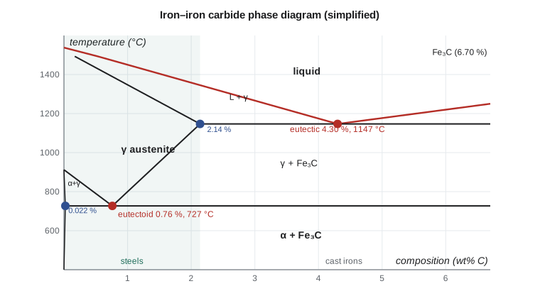
The diagram contains four solid phases. Alpha ferrite is BCC iron with at most 0.022 wt% C dissolved, at 727 °C; it is soft, ductile and magnetic below 768 °C. Austenite, gamma iron, is FCC and can dissolve up to 2.14 wt% C at 1147 °C; it is not stable in plain carbon steel at room temperature, but large additions of nickel and manganese stabilize it, which is how austenitic stainless steels are made. Delta ferrite is the high-temperature BCC phase and matters mainly in welding. Cementite is hard and brittle and strengthens steel when it is finely distributed.
Two invariant reactions are important. The eutectic, at 4.30 wt% C and 1147 °C, matters for cast irons. The eutectoid, at 0.76 wt% C and 727 °C, matters for all steels:
Because the ferrite and cementite form together from a single phase, the carbon atoms need to diffuse only short distances, and the product is a fine layered structure of alternating ferrite and cementite plates called pearlite, named for its mother-of-pearl appearance under the microscope. By the lever rule, pearlite is about 89 percent ferrite and 11 percent cementite by mass, so the ferrite plates are roughly eight times thicker than the cementite plates. Pearlite combines the ductility of ferrite with the strength of cementite.
Slow cooling: hypoeutectoid and hypereutectoid steels
A steel with less than 0.76 wt% C is hypoeutectoid. Cooling slowly from the austenite region, it crosses the boundary into the ferrite plus austenite region, and proeutectoid ferrite begins to form at the austenite grain boundaries. The remaining austenite becomes richer in carbon until, at 727 °C, it reaches 0.76 percent and transforms to pearlite. The final structure is proeutectoid ferrite plus pearlite, and the fraction of pearlite, and with it the strength and hardness, increases with carbon content. A steel with more than 0.76 percent is hypereutectoid; it forms proeutectoid cementite at the austenite grain boundaries before the rest transforms to pearlite. The brittle cementite network makes slowly cooled hypereutectoid steels less tough, so tool and bearing steels are given special treatments to break it into spheroids.
Worked problem
Microconstituents in a 0.40 % carbon steel
A plain carbon steel with 0.40 wt% C is cooled slowly from 900 °C. Just below 727 °C, find (a) the fractions of proeutectoid ferrite and pearlite, and (b) the total fractions of ferrite and cementite.
Show solution
- (a) Just above 727 °C, the steel is proeutectoid ferrite (0.022 wt% C) and austenite of eutectoid composition (0.76 wt% C), and all of that austenite becomes pearlite:
- \[W_{\text{pearlite}} = \frac{0.40 - 0.022}{0.76 - 0.022} = 0.512 \qquad W_{\alpha,\,\text{pro}} = 0.488\]
- (b) Just below 727 °C, the tie line runs from ferrite (0.022) to cementite (6.70):
- \[W_{\alpha} = \frac{6.70 - 0.40}{6.70 - 0.022} = 0.943 \qquad W_{\text{Fe}_3\text{C}} = 0.057\]
Answer: About half the steel is pearlite, but less than 6 percent is cementite. The difference between microconstituents (proeutectoid ferrite and pearlite) and phases (ferrite and cementite) is worth keeping clear; exam questions test it often.
# Iron-carbon lever rule and tempering equivalence (Hollomon-Jaffe parameter)
import math

Ca, Ce, Cc = 0.022, 0.76, 6.70     # wt% C: ferrite limit at 727 C, eutectoid, cementite

def microconstituents(C0):
    """Fractions just below 727 C for slowly cooled plain carbon steel."""
    if C0 <= Ca:
        return {'ferrite': 1.0}
    if C0 < Ce:                      # hypoeutectoid
        Wp = (C0 - Ca) / (Ce - Ca)
        out = {'proeutectoid ferrite': 1 - Wp, 'pearlite': Wp}
    elif C0 == Ce:
        out = {'pearlite': 1.0}
    else:                            # hypereutectoid (up to 2.14 wt% C)
        Wp = (Cc - C0) / (Cc - Ce)
        out = {'proeutectoid cementite': 1 - Wp, 'pearlite': Wp}
    out['total ferrite'] = (Cc - C0) / (Cc - Ca)
    out['total cementite'] = 1 - out['total ferrite']
    return out

for C0 in (0.20, 0.40, 0.60, 0.76, 1.00):
    m = microconstituents(C0)
    print(f"{C0:.2f} wt% C: " + ", ".join(f"{k} {v:.3f}" for k, v in m.items()))

# Pearlite itself: fraction of ferrite and cementite in the eutectoid
Wf = (Cc - Ce) / (Cc - Ca)
print(f"\npearlite is {Wf:.3f} ferrite and {1 - Wf:.3f} cementite by mass")
print(f"plate thickness ratio (ferrite : cementite) about {Wf / (1 - Wf) * 7.7 / 7.87:.1f} : 1 "
      "(densities 7.87 and 7.7 g/cm3)")

# Tempering: Hollomon-Jaffe parameter P = T (C + log10 t), T in K, t in h, C about 20
def P(Tc, t_h, C=20.0):
    return (Tc + 273.15) * (C + math.log10(t_h))

def time_for(Pval, Tc, C=20.0):
    return 10 ** (Pval / (Tc + 273.15) - C)

ref = P(540, 2.0)
print(f"\ntempering 2 h at 540 C gives P = {ref:,.0f}")
for Tc in (500, 520, 560, 580, 600):
print(f" equivalent time at {Tc} C: {time_for(ref, Tc):8.2f} h")0.20 wt% C: proeutectoid ferrite 0.759, pearlite 0.241, total ferrite 0.973, total cementite 0.027 0.40 wt% C: proeutectoid ferrite 0.488, pearlite 0.512, total ferrite 0.943, total cementite 0.057 0.60 wt% C: proeutectoid ferrite 0.217, pearlite 0.783, total ferrite 0.913, total cementite 0.087 0.76 wt% C: pearlite 1.000, total ferrite 0.889, total cementite 0.111 1.00 wt% C: proeutectoid cementite 0.040, pearlite 0.960, total ferrite 0.854, total cementite 0.146 pearlite is 0.889 ferrite and 0.111 cementite by mass plate thickness ratio (ferrite : cementite) about 7.9 : 1 (densities 7.87 and 7.7 g/cm3) tempering 2 h at 540 C gives P = 16,508 equivalent time at 500 C: 22.46 h equivalent time at 520 C: 6.50 h equivalent time at 560 C: 0.65 h equivalent time at 580 C: 0.22 h equivalent time at 600 C: 0.08 h
Transformation rates: isothermal transformation diagrams
The phase diagram says nothing about how fast transformations happen. Austenite transforms to pearlite by nucleation and growth, which needs diffusion of carbon. Just below 727 °C, diffusion is fast but the driving force is small, so nucleation is slow and transformation takes a long time. At lower temperatures, the driving force is larger but diffusion slower. The result is a C-shaped curve on a plot of temperature against the logarithm of time, the isothermal transformation (IT) or time–temperature–transformation (TTT) diagram, drawn for a particular steel. Its nose, where transformation starts fastest, is at around 550 °C and less than a second for plain carbon eutectoid steel.
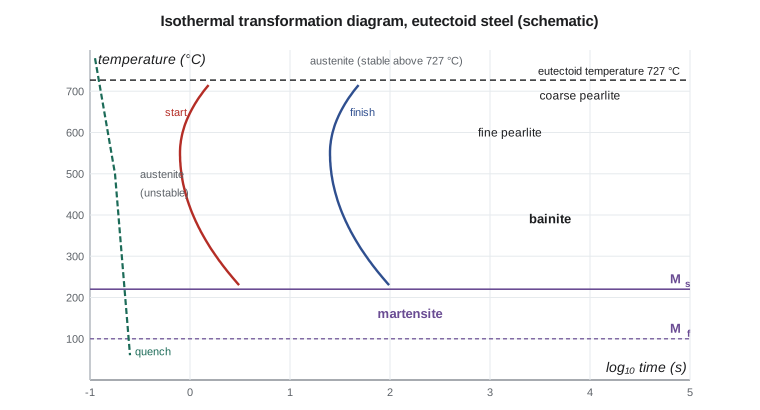
The product depends on the transformation temperature. Just below 727 °C, pearlite forms with coarse plates and is relatively soft. Near the nose it forms fine pearlite, harder and stronger. Below the nose, from about 540 °C to 250 °C, the product is bainite, a non-layered mixture of ferrite and very fine cementite particles, strong and tough. Real parts cool continuously rather than at one temperature, so engineers use continuous-cooling transformation (CCT) diagrams, which have similar shapes shifted to longer times and lower temperatures.
Martensite
If austenite is cooled so fast that it misses the nose of the curve, it has no time for carbon to diffuse. Below a temperature called the martensite start, \(M_s\), it transforms instead by a sudden shear of the lattice into martensite, a body-centred tetragonal (BCT) structure, a BCC cell stretched along one axis by the carbon trapped inside it. The transformation is diffusionless and almost instantaneous; the amount of martensite depends only on how far below \(M_s\) the steel is cooled, not on time, and it is complete at the martensite finish, \(M_f\). For high-carbon and some alloy steels, \(M_f\) is below room temperature, which leaves retained austenite, the problem Jonah checks for in carburized gears.
Martensite is the hardest structure in steel, and its hardness depends almost entirely on carbon content: roughly 45 HRC at 0.2 percent carbon, 55 to 58 at 0.4 percent and about 65 above 0.6 percent. The trapped carbon distorts the lattice and blocks dislocations, and the very fine plate or lath structure adds more strength. As-quenched martensite is also brittle and full of internal stress, and the volume increase of about 4 percent on transformation can distort or crack parts during quenching. It is almost never used without tempering.
Tempering
Tempering means reheating martensite to a temperature below 727 °C, typically 150 to 650 °C, for an hour or more. Carbon diffuses out of the strained lattice to form very fine carbide particles, internal stresses relax, and the BCT structure becomes ferrite. The result, tempered martensite, is slightly less hard than martensite but far tougher. Higher tempering temperatures and longer times give lower hardness and greater toughness. Gears and bearings are tempered at about 150 to 200 °C to keep high surface hardness; shafts and bolts are tempered at 400 to 650 °C for a balance of strength and toughness. Temperature and time trade against each other, a relationship captured by the Hollomon–Jaffe tempering parameter \(P = T(C + \log t)\), with \(T\) in kelvin, \(t\) in hours and \(C\) about 20 for many steels.
Worked problem
Equivalent tempering time
Kestrel's shafts are normally tempered for 2 h at 540 °C. A furnace fault leaves it controlling at 560 °C. Using the Hollomon–Jaffe parameter with \(C = 20\), what time at 560 °C gives the same result?
Show solution
- \(P = (540 + 273)(20 + \log 2) = 813.15 \times 20.301 = 16\,508\).
- \[\log t = \frac{16\,508}{833.15} - 20 = -0.186 \quad\Rightarrow\quad t = 0.65\ \text{h}\]
Answer: A 20 °C increase cuts the equivalent time to about a third. Tempering is very sensitive to temperature, which is why tempering furnaces are surveyed and controlled tightly, and why Kestrel checks the hardness of every batch.
Some alloy steels lose toughness if tempered in the range of about 250 to 400 °C, or if held or slowly cooled through about 375 to 575 °C, through mechanisms called tempered martensite embrittlement and temper embrittlement. Specifications avoid those ranges, and Charpy tests on heat-treated samples catch problems.
Hardenability
Hardenability is the ability of a steel to form martensite to a depth when quenched. It is not the same as hardness, which is set by carbon content. A plain carbon steel has low hardenability: its TTT curve is so far to the left that only the surface of a large part cools fast enough to miss the nose. Alloying elements such as chromium, molybdenum, nickel and manganese, and tiny amounts of boron, slow the pearlite and bainite reactions and shift the curves to the right, so martensite can form in thicker sections or with a gentler quench. That is why Kestrel's shafts are made from a chromium–molybdenum steel: a 50 mm shaft of plain 0.4 percent carbon steel would harden only near its surface even in water, while the alloy steel through-hardens in oil.
Hardenability is measured by the Jominy end-quench test. A standard bar 25 mm in diameter is austenitized and one end sprayed with water. The cooling rate decreases with distance from the quenched end, and hardness is measured along the bar. A steel with high hardenability keeps its hardness far from the end; one with low hardenability drops off quickly. Jominy curves let engineers predict the hardness at the centre of real parts of different sizes quenched in different media.
The quenching medium matters too. Water and brine quench fastest but cause the largest thermal gradients and the greatest risk of distortion and cracking. Oil is slower and gentler; polymer solutions are adjustable between the two. Sharp corners, sudden changes in section and holes near edges concentrate quench stresses, so designers of heat-treated parts use generous radii, as they do for fatigue.
The main heat treatments
- Full annealing: heat into the austenite region, then cool slowly in the furnace to give coarse pearlite; soft and easy to machine and form.
- Normalizing: heat into the austenite region and cool in still air to give fine pearlite and a refined grain size; used after forging and welding.
- Hardening and tempering: austenitize, quench to form martensite, then temper to the required balance of strength and toughness.
- Austempering: quench into a salt bath held just above Mₛ and hold until the austenite transforms to bainite; low distortion and good toughness.
- Spheroidizing: hold just below 727 °C for many hours so cementite forms spheres; makes high-carbon steels machinable and formable.
- Surface hardening: carburizing, carbonitriding, nitriding, induction and flame hardening produce a hard case on a tough core.
| Kestrel part | Steel type | Treatment | Typical result |
|---|---|---|---|
| PTO shaft | 0.4 % C, Cr–Mo alloy | Oil quench and temper at about 550 °C | 28–34 HRC through the section |
| Gear | 0.2 % C, Ni–Cr–Mo alloy | Carburize, quench, temper at about 170 °C | Case 58–62 HRC, core 30–40 HRC |
| Splined shaft end | 0.4 % C, Cr–Mo alloy | Induction harden and temper | Surface about 55 HRC to 2–3 mm depth |
| Hitch pin | 0.4 % C plain carbon | Cold drawn, then induction hardened | Hard wear surface on a strong core |
| Frame plate | 0.1 % C microalloyed | Controlled rolling, no further heat treatment | Fine-grained ferrite and pearlite |
Common mistakes
MistakeConfusing hardness with hardenability.
InsteadHardness depends on carbon; hardenability, the depth of hardening, depends mainly on alloying.
MistakeMixing up microconstituents and phases in lever-rule problems.
InsteadPearlite is a microconstituent of two phases, ferrite and cementite.
MistakeThinking martensite forms by diffusion over time at a fixed temperature.
InsteadMartensite forms by shear; its amount depends on how far below Mₛ the steel is cooled.
MistakeUsing as-quenched martensite in service.
InsteadAlways temper; as-quenched martensite is brittle and highly stressed.
MistakeAssuming a faster quench is always better.
InsteadSevere quenches raise distortion and cracking risk; choose a steel with enough hardenability for a gentler quench.
Summary and key terms
- The Fe–Fe₃C diagram has ferrite, austenite, delta ferrite and cementite; the eutectoid is at 0.76 % C and 727 °C.
- Pearlite is a layered mixture of about 89 % ferrite and 11 % cementite.
- Hypoeutectoid steels form proeutectoid ferrite plus pearlite; hypereutectoid steels form proeutectoid cementite plus pearlite.
- TTT and CCT diagrams show how transformation products depend on temperature and time.
- Martensite forms by diffusionless shear below Mₛ; its hardness depends on carbon content.
- Tempering trades hardness for toughness; temperature and time are combined in the Hollomon–Jaffe parameter.
- Hardenability, measured by the Jominy test, is raised by alloying elements.
- Ferrite
- BCC iron with very little dissolved carbon.
- Austenite
- FCC iron, stable at high temperatures, dissolving up to 2.14 % carbon.
- Cementite
- The hard, brittle iron carbide Fe₃C.
- Pearlite
- A layered mixture of ferrite and cementite formed by the eutectoid reaction.
- Bainite
- A fine non-layered mixture of ferrite and carbide formed below the TTT nose.
- Martensite
- A hard BCT phase formed from austenite by diffusionless transformation.
- Tempering
- Reheating martensite to improve toughness at some loss of hardness.
- Hardenability
- The ability of a steel to form martensite to a depth on quenching.
Practice problems
Work each problem on paper first, then reveal the answer to check.
Find the fractions of proeutectoid ferrite and pearlite in a 0.25 % C steel cooled slowly.
Show answer
Pearlite 0.309; proeutectoid ferrite 0.691.
Find the fraction of proeutectoid cementite in a slowly cooled 1.20 % C steel.
Show answer
(1.20 − 0.76)/(6.70 − 0.76) = 0.074.
Why can't plain carbon steel be through-hardened in a 75 mm shaft?
Show answer
Its TTT nose is too close to zero time; the centre cools too slowly and forms pearlite.
What is the main structural difference between bainite and pearlite?
Show answer
Pearlite has alternating plates of ferrite and cementite; bainite has fine carbide particles in ferrite without the layered structure.
Using the Hollomon–Jaffe example, what time at 520 °C matches 2 h at 540 °C?
Show answer
About 6.5 h.
Run the program for a 0.30 % C steel. What fraction is pearlite?
Show answer
About 0.38.
Lesson quiz · 5 questions
Score 60% or more to complete this lesson.
Create a free account to save your progress, take quizzes and earn a certificate.