
LVT-210 · Lesson 8 of 12 · 20 min
Fusion splicing
A fusion splice joins two fibres by melting their ends together with an electric arc, so the light passes from one to the other as if they were a single strand. A good splice loses only a few hundredths of a decibel and reflects almost nothing. It is the lowest-loss, most reliable joint in fibre work, and it is the core skill of the fibre crew. This lesson follows Maya through her first day of splicing at the Hartwell warehouse, where the 12-strand singlemode cable is spliced to LC pigtails in the new wall enclosure at the far end, and then through the larger job of splicing the Riverside cables.
The fusion splicer
A fusion splicer is a portable machine about the size of a large lunch box. Inside, two V-grooves or clamps hold the fibre ends facing each other between two electrodes. Cameras look at the fibres from two directions at right angles, and motors move them in three axes. A modern core-alignment splicer finds the cores in the camera images and lines them up to a fraction of a micrometre before firing the arc. Cheaper cladding-alignment splicers line up the outside of the glass instead, which works well with good fibre but cannot correct for a core that is slightly off-centre in its cladding. For singlemode backbones, Cobalt Line uses core-alignment splicers.
The splicer also contains a heat-shrink oven for the splice protectors, a screen, and a set of programs for different fibre types. The arc's strength and duration are adjusted by an arc calibration, which the operator runs at the start of each day and whenever the altitude, temperature or humidity changes markedly, because the arc behaves differently in different air. The electrodes wear and are replaced after a few thousand arcs.
The splice sequence
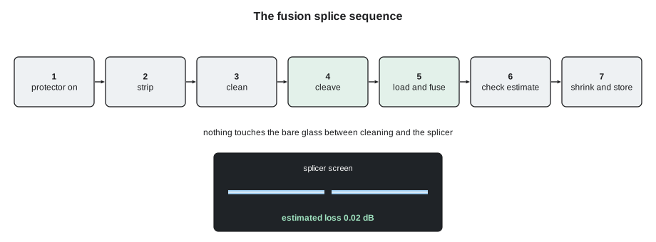
Every splice follows the same sequence, and Hollis has Maya say the steps aloud for her first dozen splices. The order matters because the bare glass is at its most fragile between stripping and protecting it, and every step that touches it is a chance for damage or dirt.
- Slide the heat-shrink protector onto one of the fibres first. It cannot be added after the splice.
- Strip the coating with a fibre stripper, removing about 30 to 40 mm (1.2 to 1.6 in) of 250 µm coating, or the buffer and coating together on tight-buffered fibre.
- Clean the bare glass with a lint-free wipe and 99 percent isopropyl alcohol, pulling the fibre through the wipe once. Do not touch the glass afterwards.
- Cleave the fibre in a precision cleaver, which scores it and breaks it to leave a flat end face square to the axis. Put the scrap straight into the waste container.
- Place the fibre in the splicer's V-groove without letting the cleaved end touch anything. Repeat for the other fibre.
- Close the lid; the splicer aligns, checks the cleave angles and end faces, fuses and estimates the loss.
- Check the result on screen, remove the fibre, centre the protector over the splice and shrink it in the oven.
- Let the protector cool, then place it in the tray's splice holder and route the slack.
The cleave
The cleave is the step that decides most splices. A good cleave is flat and square to the fibre axis, with a cleave angle of less than about 1°, and ideally under half a degree. A poor cleave, with a lip, a chip, a hackle or a steep angle, makes a splice with higher loss or a bubble inside it. The splicer measures the cleave angle of each fibre in its camera image and refuses to fuse if either exceeds its limit, which is usually set between 1° and 2° for singlemode.
Cleavers need care. The blade is a small rotating wheel of hard metal or diamond, and it is turned to a fresh position after a set number of cleaves. Glass dust and scraps are cleaned from the clamps and the anvil. A cleaver that starts producing poor cleaves is usually due for a blade rotation or a cleaning, not a new technique. Maya keeps a tally of her cleave angles on the first day, as Hollis asks, and notices that her rejects come in clusters, every one after she put the cleaver down on the tailgate without closing it.
What makes a splice lose light
A splice loses light for three main reasons. A small offset between the two cores lets part of the light miss the receiving core. A difference in the mode field diameter, the effective width of the light in the core, between the two fibres means the light spreads or squeezes as it crosses. And defects in the joint itself, such as bubbles, a narrowed neck or a bend in the fused glass, scatter light. The first two can be calculated, and the code below uses the standard formula for two singlemode fibres to show why core alignment matters.
Here w₁ and w₂ are the mode field radii of the two fibres, half of the mode field diameter, and d is the lateral offset between the cores. For standard singlemode fibre at 1310 nm, the mode field diameter is about 9.2 µm, so the radius is about 4.6 µm.
import math
# Splice loss from core offset and mode field mismatch (singlemode, Gaussian approximation)
def splice_loss(d, mfd1, mfd2):
    w1, w2 = mfd1 / 2, mfd2 / 2
    t = (2 * w1 * w2 / (w1**2 + w2**2)) ** 2 * math.exp(-2 * d**2 / (w1**2 + w2**2))
    return abs(-10 * math.log10(t))
print("offset (um)   loss at 1310 nm (dB)   loss at 1550 nm (dB)")
for d in (0.0, 0.2, 0.5, 1.0, 1.5, 2.0):
    print(f"{d:8.1f} {splice_loss(d, 9.2, 9.2):18.3f} {splice_loss(d, 10.4, 10.4):20.3f}")
# Two different fibres: a standard fibre spliced to a bend-insensitive fibre with a smaller MFD
print(f"MFD 9.2 to 8.6 um, no offset: {splice_loss(0, 9.2, 8.6):.3f} dB")offset (um) loss at 1310 nm (dB) loss at 1550 nm (dB)
0.0 0.000 0.000
0.2 0.008 0.006
0.5 0.051 0.040
1.0 0.205 0.161
1.5 0.462 0.361
2.0 0.821 0.642
MFD 9.2 to 8.6 um, no offset: 0.020 dBA core offset of half a micrometre, a hundredth of the thickness of a sheet of paper, costs about 0.05 dB. An offset of two micrometres, which a cladding-alignment splicer can produce if one fibre's core is slightly eccentric, costs about 0.8 dB. Splicing two different fibres with different mode field diameters costs a small, fixed amount even when perfectly aligned. That last result also explains a puzzle lesson 11 covers: a splice between dissimilar fibres can look like a gain on an OTDR measured in one direction.
The splicer's loss estimate
After every splice, the splicer displays an estimated loss, calculated from the camera images of the fused joint. It is useful for catching bad splices at once: anything above the crew's threshold, 0.05 dB on singlemode for Hollis's crew, is broken out and remade on the spot while the fibre is in the machine. But the estimate is not a measurement. It cannot see the light, and a splice that looks good to the cameras can still lose more than the estimate says. The real splice loss comes from the OTDR in lesson 11, averaged in both directions.
The splicer also runs a proof test after each splice: as the fibre is released, the clamps pull it with a small, fixed tension, enough to break a weak splice before it is protected rather than after it is stored in a tray. A splice that breaks in the proof test was going to fail eventually, and is simply remade.
Protecting and storing the splice
The fused glass is bare and fragile. A heat-shrink splice protector, a short sleeve of heat-shrinkable plastic with a stainless steel or ceramic rod and a meltable inner tube, is slid over the splice and shrunk in the splicer's oven. The inner tube melts around the glass, the rod keeps the splice straight and the outer sleeve shrinks tight. The protected splice is then pressed into its numbered slot in the splice tray's holder, and the fibre slack on each side is wound into the tray as lesson 5 described.
Ribbon splices, in high-count cables, are protected in wider sleeves holding a whole ribbon of twelve fibres. Some trays use crimp-on protectors or bonded protectors instead of heat-shrink. Whatever the type, the protector goes into the tray with no bend in the bare fibre at either end.
Setting up to splice
Splicing is done on a stable, clean surface out of the wind and dust. Indoors, the crew sets up a folding table beside the enclosure with a black mat, the splicer, the cleaver, the stripper, the alcohol dispenser and the waste container, as lesson 3 described. Outdoors, splicing is done in a splicing trailer, a van with a work table, or a tent beside the handhole, with the cable brought up from the hole using the slack left for that purpose. At Riverside, Hollis splices in the gymnasium room G1 and in room 1A, bringing the cable ends to the table on their slack.
# Planning the Riverside splicing: splices, time and expected loss
strands = 24 + 12            # OS2 and OM4 strands
ends = 2                     # spliced to pigtails at both ends
MIN_PER_SPLICE = 3.5         # experienced splicer, including protection
REMAKE_RATE = 0.08           # fraction of splices remade
SETUP_MIN = 45               # setting up and arc calibration at each end
splices = strands * ends
minutes = splices * MIN_PER_SPLICE * (1 + REMAKE_RATE) + ends * SETUP_MIN
print(f"splices: {splices}, about {minutes / 60:.1f} hours of splicing")
print(f"protectors to bring: {int(splices * (1 + REMAKE_RATE)) + 10}")
estimates = [0.02, 0.01, 0.03, 0.02, 0.06, 0.02, 0.01, 0.02, 0.04, 0.02, 0.01, 0.03]
remake = [i + 1 for i, e in enumerate(estimates) if e > 0.05]
print(f"tray 1 estimates: average {sum(estimates) / len(estimates):.3f} dB, remake splice(s) {remake}")splices: 72, about 6.0 hours of splicing protectors to bring: 87 tray 1 estimates: average 0.024 dB, remake splice(s) [5]
Worked problem
A bubble on the screen
On splice 9 of the Riverside OS2 tray 1, the splicer's image shows a small dark bubble in the joint and an estimate of 0.21 dB. What should Maya do?
Show solution
- A bubble usually comes from a poor cleave or dirt on the end face.
- The estimate is well above the crew's 0.05 dB threshold.
- Break the splice before protecting it, strip back if needed, re-clean and re-cleave both fibres, and splice again.
- If bubbles repeat, clean the cleaver and the V-grooves and check the electrodes and arc calibration.
Answer: Maya remakes the splice; the second attempt estimates 0.02 dB with no bubble.
Splicing in difficult conditions
Fusion splicers are designed for the field, but they have limits. Wind blows dust into the V-grooves and cools the arc; cold slows the heat-shrink oven and stiffens the fibre coatings; humidity changes the arc; and vibration from traffic or machinery can upset the alignment. Outdoor splicing is done in a splicing trailer or a tent with the splicer on a stable table, and the splicer is allowed to reach the temperature of the space before arc calibration. In cold weather, the protectors take longer to shrink, and the splicer's oven program is lengthened rather than cutting the cycle short.
At Riverside, the handhole 1 closure is spliced in late autumn from the splicing trailer, with the closure's cable ends brought up on their slack. Maya calibrates the arc after the trailer's heater has run for half an hour, and again at midday when the temperature in the trailer has risen. Her first splices of the day estimate at 0.06 to 0.08 dB, above the crew's threshold; after the second calibration they settle at 0.02 to 0.03 dB. The lesson she writes in her logbook is that a calibration done in a cold trailer is a calibration for a cold trailer.
The closure itself is sealed according to its instructions: the cable entries are wrapped or gasketed, the dome or shell is clamped onto its base, and some closures are pressure-tested with a hand pump and soapy water at the valve to check the seal. A closure that lets water in can freeze around the splice trays, and ice can break fibres. The finished closure is secured on its bracket in the handhole with the service loops, so it does not rest on the floor where water collects.
Common mistakes
MistakeForgetting to slide the splice protector on before splicing.
InsteadPut the protector on first; it cannot be added afterwards.
MistakeTouching the bare glass after cleaning it.
InsteadClean once, cleave, and place the fibre in the splicer without touching the end.
MistakeTrusting the splicer's loss estimate as a measurement.
InsteadUse it to catch bad splices; measure real loss with an OTDR in both directions.
MistakeIgnoring clusters of bad cleaves.
InsteadClean the cleaver and rotate the blade when cleave angles start to rise.
MistakeSkipping the arc calibration when conditions change.
InsteadCalibrate at the start of each day and when altitude, temperature or humidity change.
Summary and key terms
- A fusion splice melts two fibre ends together with an electric arc, giving very low loss and almost no reflection.
- Core-alignment splicers line up the cores themselves and are preferred for singlemode.
- The sequence is protector on, strip, clean, cleave, load, fuse, inspect, protect and store.
- A cleave must be flat and square, typically under 1°; the splicer rejects poor cleaves.
- Splice loss comes mainly from core offset, mode field mismatch and defects in the joint.
- The splicer's estimate catches bad splices, but real loss is measured with an OTDR in both directions.
- Splices are protected with heat-shrink sleeves and stored in numbered tray positions.
- Fusion splice
- A permanent joint made by melting two fibre ends together with an electric arc.
- Core-alignment splicer
- A splicer that images and aligns the fibre cores before fusing.
- Cleave angle
- The angle of the fibre end face from square to the axis.
- Mode field diameter
- The effective width of the light travelling in a singlemode core.
- Arc calibration
- A routine that adjusts the splicer's arc to the current conditions.
- Proof test
- A small tension applied to a finished splice to break any weak joint before it is protected.
- Splice protector
- A heat-shrink sleeve with a strength rod that protects a finished splice.
Practice problems
Work each problem on paper first, then reveal the answer to check.
What is the first step of every fusion splice?
Show answer
Slide the heat-shrink protector onto one fibre.
A splicer rejects a fibre with a 2.4° cleave angle. What next?
Show answer
Re-strip if needed, clean and re-cleave; check the cleaver if it keeps happening.
About what loss does a 1 µm core offset cause at 1310 nm?
Show answer
About 0.2 dB.
Why is the splicer's loss estimate not a final result?
Show answer
It is calculated from images, not measured with light.
Lesson quiz · 5 questions
Score 60% or more to complete this lesson.
Create a free account to save your progress, take quizzes and earn a certificate.