
LVT-210 · Lesson 12 of 12 · 19 min
Capstone: building and certifying a campus backbone
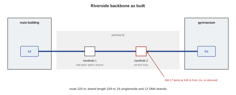
The Riverside school's campus backbone ties the season together. LVT-120 followed Sanjay's design of the route: a 320 m (1,050 ft) underground conduit from the main building's room 1A to room G1 in the gymnasium, carrying a 24-strand OS2 singlemode cable for the future and a 12-strand OM4 cable for the switches the board already owns. This course has followed the crew through its parts: the pull from the middle handhole in lesson 4, the enclosures and splice maps in lesson 5, the pigtails in lesson 7, the splicing in lesson 8 and the testing in lessons 10 and 11. This capstone follows the whole job from the start of the pull to the day the school's network technician plugs in the first switch, as Maya leads it under Hollis's supervision.
The scope and the plan
Maya's plan for the job fits on two pages, the same shape as the copper installation plan in LVT-130. The scope: pull both cables through the conduit's fabric inner duct, leave a 10 m (33 ft) service loop in each handhole and slack at each end, install a 2U rack-mount enclosure in each room, splice LC UPC singlemode pigtails to the 24 OS2 strands and LC multimode pigtails to the 12 OM4 strands at both ends, label everything to the board's TIA-606 scheme, and certify every strand with Tier 1 and Tier 2 testing. The deliverables: as-built drawings, splice maps, the test reports and OTDR traces for every strand, and the inspection images for every connector.
| Week | Work | Hold point or check |
|---|---|---|
| 1 | Locates, handhole inspection, pull both cables in two directions from handhole 1 | Pull record: swivel setting, lengths, no breakaway |
| 2 | Enclosures installed; cables secured; splicing at room 1A | First 6 splices tested before continuing |
| 2 | Splicing at room G1 | Splice maps checked against the colour code |
| 3 | Conduit damage repaired; mid-span splice closure in handhole 1 | Closure sealed and secured on its bracket |
| 3 | Tier 1 testing, both directions, both wavelengths | Reference checked at start and end of each session |
| 4 | Tier 2 OTDR testing from both ends; corrections; retests | All events within the specification's limits |
| 4 | Records, handover and walk-through with the board | Board's network technician signs acceptance |
The pull and an unwelcome surprise
The pull went as lesson 4 planned. The cables were fed from the reels at handhole 1, pulled to the gymnasium, laid out in a figure eight and pulled back to the main building. The breakaway swivel, set at 1,800 N (400 lbf), never parted, and the pull record shows the starting and ending length marks of each cable. Both cables were sealed and tagged at each end the same afternoon.
The surprise came a week later. A paving contractor working on the parking lot dug a test hole for a light standard directly over the conduit, cracked it, and pulled out a loop of the cables before stopping. Nothing was cut, but both cables had been bent sharply and stretched. Hollis's view was simple: a cable that has been pulled past its rating and kinked cannot be trusted, even if it tests well today. The board agreed. The conduit was repaired, the damaged section of both cables was cut out at handhole 1, and new cable was spliced in with a mid-span splice closure in the handhole. The splice adds one fusion splice to each strand, and the loss budget is recalculated to include it.
Splicing and records
Splicing at each end followed lesson 8, with Maya splicing room 1A and Hollis room G1, then Maya splicing the handhole 1 closure from the splicing trailer parked beside it. Each strand now has three splices: one to the pigtail at each end and one in the closure. The splice maps for both enclosures and the closure were filled in as each tray was completed, and Teo checked them against the TIA-598 colour code before each lid was closed. Every connector was inspected before it was plugged into the back of its adapter panel, and the inspection images were saved under the port identifiers.
# The Riverside budget, recalculated with the mid-span splice
STRAND_M = 329                       # fibre length from the OTDR, m
KM = STRAND_M * 0.001
CONN, SPLICE = 0.75, 0.3
NC, NS = 2, 3                        # two end connections, three splices per strand
limits = {
    "OS2 1310 nm": 0.5 * KM + CONN * NC + SPLICE * NS,
    "OS2 1550 nm": 0.5 * KM + CONN * NC + SPLICE * NS,
    "OM4 850 nm":  3.5 * KM + CONN * NC + SPLICE * NS,
    "OM4 1300 nm": 1.5 * KM + CONN * NC + SPLICE * NS,
}
for k, v in limits.items():
    print(f"{k}: limit {v:.2f} dB")
typical = 0.35 * KM + 2 * 0.25 + 3 * 0.03
print(f"expected for a good singlemode strand at 1310 nm: about {typical:.2f} dB")OS2 1310 nm: limit 2.56 dB OS2 1550 nm: limit 2.56 dB OM4 850 nm: limit 3.55 dB OM4 1300 nm: limit 2.89 dB expected for a good singlemode strand at 1310 nm: about 0.71 dB
The singlemode limit is about 2.56 dB with three splices, and a good strand should measure about 0.7 dB. The OM4 limits are higher at 850 nm, because the fibre's own attenuation allowance is larger there. Hollis sets both limits in the tester before testing, records the reference method as one cord, and checks that the multimode source is set up with the encircled flux cords.
Tier 1 results
Tier 1 testing took two sessions. All 36 strands were tested in both directions at both wavelengths, with Teo at room G1 and Maya at room 1A, each with a certification tester unit, talking by phone. Every connection was inspected before it was mated, and the reference was checked at the end of each session. The results file holds 144 loss measurements for the singlemode and 48 for the multimode.
# Summary of the Riverside Tier 1 results (selected strands and totals)
LIM_SM, LIM_MM850, LIM_MM1300 = 2.56, 3.55, 2.89
sm = {  # strand: (1310 A-B, 1310 B-A, 1550 A-B, 1550 B-A)
    "SM-01": (0.68, 0.70, 0.63, 0.66), "SM-08": (0.74, 0.71, 0.69, 0.70),
    "SM-17": (0.71, 0.73, 1.12, 1.15), "SM-20": (0.79, 0.81, 0.76, 0.77),
    "SM-24": (0.66, 0.69, 0.62, 0.64)}
mm = {"MM-01": (1.48, 1.51, 0.98, 1.00), "MM-06": (1.62, 1.66, 1.05, 1.09), "MM-12": (1.55, 1.52, 1.01, 0.99)}
for s, r in sm.items():
    worst = max(r)
    flag = "  bend? (1550 high)" if (r[2] + r[3]) / 2 - (r[0] + r[1]) / 2 > 0.3 else ""
    print(f"{s}: worst {worst:.2f} dB, margin {LIM_SM - worst:.2f} dB{flag}")
for s, r in mm.items():
    print(f"{s}: 850 nm worst {max(r[:2]):.2f} (margin {LIM_MM850 - max(r[:2]):.2f}), 1300 nm worst {max(r[2:]):.2f} (margin {LIM_MM1300 - max(r[2:]):.2f})")
print("all 36 strands: PASS on loss; polarity correct on all 18 duplex pairs")SM-01: worst 0.70 dB, margin 1.86 dB SM-08: worst 0.74 dB, margin 1.82 dB SM-17: worst 1.15 dB, margin 1.41 dB bend? (1550 high) SM-20: worst 0.81 dB, margin 1.75 dB SM-24: worst 0.69 dB, margin 1.87 dB MM-01: 850 nm worst 1.51 (margin 2.04), 1300 nm worst 1.00 (margin 1.89) MM-06: 850 nm worst 1.66 (margin 1.89), 1300 nm worst 1.09 (margin 1.80) MM-12: 850 nm worst 1.55 (margin 2.00), 1300 nm worst 1.01 (margin 1.88) all 36 strands: PASS on loss; polarity correct on all 18 duplex pairs
Every strand passed. Two stood out on the summary. Strand SM-17 has about 0.42 dB more loss at 1550 nm than at 1310 nm: the signature of a bend, which lesson 11 located near handhole 2. Strand SM-20 is the one whose mid-span splice Hollis remade after the first OTDR test; its loss is slightly higher than the others but well within the limit. A pass is not the end of the story for either.
Tier 2 results and the bend at handhole 2
The OTDR traces were taken from both ends at both wavelengths with 300 m (984 ft) launch and receive cables, and the splices were analysed bidirectionally. The events on every strand were the same: the combined connector and pigtail splice at room 1A, the mid-span splice at handhole 1, and the combined connector and splice at room G1. On SM-17 there was a fourth event at 248 m (814 ft) from room 1A, non-reflective, almost invisible at 1310 nm and about 0.42 dB at 1550 nm.
Teo opened handhole 2 and found the cause. The service loop had been coiled on its bracket correctly, but when the lid was set back, the edge of the loop had been pushed down against the side of the box and one tube was pinched. Only SM-17's fibre, at the outside of the tube, was bent enough to lose light. Teo re-dressed the loop on the bracket at a larger radius and tied it clear of the lid, and the event disappeared on the retest. Hollis made a note for the as-built drawings that handhole 2 is shallow and its loop must be kept low on the bracket.
# Final check: every strand has Tier 1 and Tier 2 results, and the identifiers match the labels
labels = [f"1A-G1-SM24-{n:02d}" for n in range(1, 25)] + [f"1A-G1-OM12-{n:02d}" for n in range(1, 13)]
tier1 = set(labels) - {"1A-G1-SM24-13"}             # one file saved under a typo
tier1.add("1A-G1-SM24-31")
tier2 = set(labels)
missing1 = sorted(set(labels) - tier1)
extra1 = sorted(tier1 - set(labels))
print(f"labels: {len(labels)}, Tier 1 results: {len(tier1)}, Tier 2 results: {len(tier2)}")
print("missing Tier 1:", missing1)
print("unexpected Tier 1 identifiers:", extra1)labels: 36, Tier 1 results: 36, Tier 2 results: 36 missing Tier 1: ['1A-G1-SM24-13'] unexpected Tier 1 identifiers: ['1A-G1-SM24-31']
The cross-check found one problem, the same kind LVT-130's capstone found in copper: strand 13's Tier 1 result had been saved as strand 31. The OTDR file and the trace confirmed which strand it was, and the result was renamed with a note in the report, rather than retested, because the underlying measurement was valid.
Handover
The handover package for the board is a binder and a set of files. It contains the as-built route drawing with handhole locations and the handhole 2 note, the cable data sheets and reel prints, the pull record, the splice maps for both enclosures and the closure, the Tier 1 report for all 36 strands with the reference method and cords recorded, the OTDR traces from both ends with the bidirectional splice analysis, the inspection images for every connector, and the labelling schedule. The school board's network technician, who will plug in the first switch, walks the route with Maya and checks the enclosures and labels against the records before signing the acceptance form.
The first switch link comes up at 10 Gb/s on the OM4 the same afternoon. The singlemode strands are capped and dark, waiting for the day the board replaces its switches. When that happens, a technician will be able to look up any strand, see exactly what is behind each port, and know from the records what the link measured on the day it was built.
Worked problem
Would the link carry a future 100 Gb/s connection?
The board's future plan is 100 Gb/s long-reach optics on the singlemode strands. Their data sheet allows a channel loss of several decibels, and the worst singlemode strand, after the handhole 2 repair, measures 0.81 dB. The channel will add two patch cords. Will it work, and what will decide it?
Show solution
- The installed links are 0.7 to 0.8 dB, far below the optics' allowance.
- Two patch cords add two more mated connections, each well under 0.5 dB if clean.
- Singlemode bandwidth is not a limit over 329 m (1,079 ft); the reach of long-reach optics is many kilometres.
- The deciding factor will be cleanliness: every new cord and port must be inspected before it is connected.
Answer: Yes. The loss, length and fibre type all allow it; the crew's records show it, and clean connections will keep it so.
Common mistakes
MistakeAccepting a cable that has been overloaded or kinked because it still tests.
InsteadReplace the damaged section; stressed glass can fail later.
MistakeLeaving the budget unchanged after adding a splice.
InsteadRecalculate the limit for the link as built.
MistakeTreating a passing strand with a 1550 nm excess as finished.
InsteadFind and fix the bend; it will only get worse.
MistakeRetesting a link because its result was saved under the wrong name.
InsteadConfirm the identity from the other records and rename it with a note.
MistakeHanding over results without the method, cords and limits.
InsteadInclude them with every result so the report can be checked.
Summary and key terms
- A campus backbone job brings together planning, pulling, enclosures, splicing, inspection and two tiers of testing.
- Damaged cable is replaced, not trusted, and the budget is recalculated for the link as built.
- Splice maps, inspection images and identifiers are recorded as the work is done.
- Tier 1 results show loss, length and polarity; Tier 2 traces show where every event is.
- A passing strand with extra loss at 1550 nm still has a bend to find and fix.
- A cross-check of results against labels catches naming errors before handover.
- The handover package lets the owner and future technicians see exactly what was built and how it measured.
- Mid-span splice closure
- A sealed enclosure in a handhole or vault where a cable is spliced between its ends.
- As-built drawing
- A drawing updated to show the installation exactly as it was built.
- Acceptance
- The owner's formal confirmation that the work meets the specification.
- Handover package
- The records, reports and drawings given to the owner at the end of a job.
- Bidirectional analysis
- OTDR analysis that averages each event measured from both ends.
Practice problems
Work each problem on paper first, then reveal the answer to check.
A singlemode outside plant link of 0.45 km has 2 connector pairs and 3 splices. What is its budget?
Show answer
0.45 × 0.5 + 1.5 + 0.9 = 2.63 dB.
Why was the damaged section of the Riverside cable replaced even though nothing was cut?
Show answer
It had been overloaded and kinked; stressed glass can fail later.
What does a non-reflective event that appears only at 1550 nm suggest?
Show answer
A bend or pinch at that point.
What should the handover package include for every strand?
Show answer
Its Tier 1 result with the method, cords and limit, its OTDR traces, and its inspection images.
Lesson quiz · 5 questions
Score 60% or more to complete this lesson.
Create a free account to save your progress, take quizzes and earn a certificate.