
LVT-210 · Lesson 7 of 12 · 20 min
Field termination: pre-terminated, splice-on and mechanical connectors
Twenty years ago, most fibre in buildings was terminated in the field by gluing a connector onto each fibre with epoxy, curing it in an oven and polishing the end face by hand on a sheet of lapping film. It took skill, time and a steady hand, and the results varied with all three. Today, the crew rarely polishes a connector. Connectors are made and polished in a factory, and the field work is choosing how to bring that factory connector onto the installed fibre. This lesson compares the four ways the crew does it: pre-terminated assemblies, fusion-spliced pigtails, splice-on connectors and mechanical connectors, and covers the occasional repair with epoxy and polish.
Four ways to put a connector on a fibre
| Method | What happens in the field | Typical loss | Best for |
|---|---|---|---|
| Pre-terminated assembly | Nothing: factory-terminated cable is pulled and plugged in | Factory-tested, often low-loss grade | Data rooms, known lengths, fast schedules |
| Fusion-spliced pigtail | A factory connector on a short fibre is fused to each strand in a tray | Connector plus a splice of about 0.05 dB | Loose-tube cable, backbones, high counts |
| Splice-on connector | The fibre is fused directly to a short stub inside the connector body | Close to a factory connector | Tight-buffered cable, repairs, few strands |
| Mechanical connector | The fibre is cleaved and pushed into a pre-polished connector with gel | Higher, typically 0.3 to 0.5 dB | Quick repairs and small jobs without a splicer |
| Epoxy and polish | Adhesive, cure and hand polish | Varies with skill | Repairs and unusual connectors |
The choice is made by the designer and the contractor together, and it depends on the cable, the number of strands, the schedule and the equipment the crew owns. On this season's jobs, St. Brendan's data room uses pre-terminated trunks, the Riverside and Hartwell cables are terminated with fusion-spliced pigtails, the Kellerman backbone uses splice-on connectors, and Juniper Point needs two mechanical connectors for a repair on a damaged spare strand.
Pre-terminated assemblies
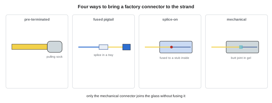
A pre-terminated assembly is a cable that arrives from the factory already terminated and tested, with its connectors protected inside a pulling sock. The installer pulls it, removes the sock and plugs the connectors into cassettes or adapter panels. There is no splicing or polishing on site, and the factory test report shows the loss of every connector. St. Brendan's data room uses OM4 and singlemode MPO trunks of 12 and 24 strands between the main distribution rack and the equipment rows, with MPO-to-LC cassettes at each end.
The catch is length. A pre-terminated trunk must be ordered at its finished length before the pathway is built, so the measurement has to be right, and any excess must be stored somewhere. Dev and Hollis measure every route at St. Brendan's with a measuring wheel along the actual tray path, add the drops at each end and a storage allowance, and round up to the manufacturer's standard length increments. The connectors are also the most vulnerable part of the cable during the pull, so the sock stays on until the trunk is in its final position, and the trunk is pulled with the manufacturer's pulling grip, never by the connectors.
# Ordering pre-terminated trunks: measured route plus drops and storage
STEP = 1.0          # manufacturer length increment, m
DROP = 2.5          # rack drop and routing at each end, m
STORE = 1.5        # storage allowance, m
routes = {"MDA to row 1": 14.2, "MDA to row 2": 18.7, "MDA to row 3": 23.4, "row 1 to row 3": 11.6}
for name, measured in routes.items():
    need = measured + 2 * DROP + STORE
    order = -(-need // STEP) * STEP
print(f"{name:15s} measured {measured:5.1f}, needed {need:5.1f}, order {order:5.1f} m, store {order - measured - 2 * DROP:4.1f} m")MDA to row 1 measured 14.2, needed 20.7, order 21.0 m, store 1.8 m MDA to row 2 measured 18.7, needed 25.2, order 26.0 m, store 2.3 m MDA to row 3 measured 23.4, needed 29.9, order 30.0 m, store 1.6 m row 1 to row 3 measured 11.6, needed 18.1, order 19.0 m, store 2.4 m
Fusion-spliced pigtails
A pigtail is a short length of tight-buffered fibre, usually 1 to 2 m (3 to 6 ft), with a factory-polished connector on one end. In the enclosure, each strand of the installed cable is fusion-spliced to a pigtail, the splice is protected in the tray, and the pigtail's connector is plugged into the back of the adapter panel. The result is a factory connector on every strand with a low-loss splice behind it. For loose-tube cable, whose bare fibres cannot be connectorized directly, pigtails are the standard method.
Pigtails come in packs of 12, in the TIA-598 colours, so pigtail number 7 is red and is spliced to strand 7. Hollis's crew uses LC UPC singlemode pigtails at Riverside and Hartwell, and LC multimode pigtails for the Riverside OM4. The pigtails are cut to length so that, after looping in the tray, they reach their adapter without excess. The cut-off ends of the pigtails go in the fibre waste container like every other scrap. Lesson 8 covers the splicing itself.
Splice-on connectors
A splice-on connector combines the two steps. The connector body contains a short factory-polished stub of fibre. The installer strips and cleaves the field fibre, places it in the fusion splicer opposite the stub, fuses them, and then assembles the connector body around the splice, which sits inside the connector's boot or body instead of in a tray. There is no splice tray and no pigtail to route, so the enclosure is simpler, and the loss is close to that of a factory connector. The trade-off is that each connector needs a fusion splicer and a connector-specific holder, and a failed splice means a new connector.
The Kellerman backbone is a 24-strand tight-buffered cable between the entrance room and room 6A, in enclosures with no room for trays. Splice-on LC connectors are fused directly to each 900 µm buffered strand. Maya terminates the room 6A end while Hollis does the entrance room, and Maya's first six connectors are tested before she does the rest, the same rule LVT-130 used for copper terminations.
Mechanical connectors
A mechanical connector also has a factory-polished stub inside, but the field fibre is not fused to it. Instead, the field fibre is cleaved, pushed into the connector until it butts against the stub in a V-groove or alignment tube, and clamped. A drop of index-matching gel between the two fibre ends fills the gap and reduces reflection. Mechanical connectors need only a stripper, a good cleaver and the connector's assembly tool. They are fast and useful for repairs and small jobs, but their loss and reflectance are higher than fused connectors, and some degrade with temperature cycling as the gel ages. Many specifications do not allow them on backbones.
At Juniper Point, one spare strand in the old enclosure was found broken just behind its connector. It is a spare in a building that has no other fibre to spare, so the property manager wants it restored, and a fusion splicer is not on site that day. Hollis has Teo install a mechanical LC connector on each end of the shortened strand, tests it, and records the result as a temporary repair to be replaced with splice-on connectors on the next visit.
Epoxy and polish
The traditional method is still used for repairs, unusual connectors and some training. The fibre is stripped and cleaned, a two-part epoxy is injected into the connector's ferrule, the fibre is pushed through, and the epoxy is cured, either in a curing oven or at room temperature with a slower adhesive. The excess fibre is scribed and snapped off at the ferrule tip, and the end face is polished on progressively finer lapping films, held square in a polishing puck, until it passes inspection. A good result is as low-loss as a factory connector; a hurried result is not. Hollis has her apprentices practise on scrap until their connectors pass inspection three times in a row, then rarely uses the method again.
Choosing and checking
# Comparing termination methods for one 24-strand link (both ends terminated)
methods = {
    "fusion pigtails":   {"conn": 0.25, "splice": 0.05, "minutes": 6.0},
    "splice-on":         {"conn": 0.20, "splice": 0.00, "minutes": 7.0},
    "mechanical":        {"conn": 0.45, "splice": 0.00, "minutes": 4.0},
    "pre-terminated":    {"conn": 0.15, "splice": 0.00, "minutes": 0.5},
}
STRANDS = 24
LENGTH_KM = 0.048       # link length, km
ATT = 0.4              # dB/km, singlemode at 1310 nm
for name, m in methods.items():
    # each end: one mated connection at the panel plus any splice behind it
    loss = LENGTH_KM * ATT + 2 * (m["conn"] + m["splice"])
    hours = 2 * STRANDS * m["minutes"] / 60
print(f"{name:16s} expected loss {loss:.2f} dB, field time about {hours:4.1f} h for both ends")fusion pigtails expected loss 0.62 dB, field time about 4.8 h for both ends splice-on expected loss 0.42 dB, field time about 5.6 h for both ends mechanical expected loss 0.92 dB, field time about 3.2 h for both ends pre-terminated expected loss 0.32 dB, field time about 0.4 h for both ends
The comparison for the Kellerman backbone, about 48 m (157 ft) long, shows why the choice is rarely about loss on a short link: every method comes in far under any loss budget. The decision is about the cable type, the enclosure space, the schedule and the long-term reliability the owner wants. On a long campus link with a tight budget, the extra loss of mechanical connectors could matter, and on a data room with fixed lengths, the time saved with pre-terminated trunks is decisive.
Whatever the method, the work is checked in the same way. Every connector end face is inspected before it is connected, as lesson 9 describes, and every strand is tested end to end, as lessons 10 and 11 describe. Terminations made in the field are recorded in the splice map and the test results, with the method used, so that anyone who works on the link later knows what is behind each port.
Worked problem
Repair or replace at Juniper Point
The mechanical repair on the Juniper Point spare strand tested at 0.48 dB per connector, with reflectance of −42 dB. The building's systems need the strand for a camera link at 1 Gb/s on OM3 over 74 m (243 ft), with a loss budget of several decibels. Is the repair acceptable, and what should happen next?
Show solution
- The total added loss is about 0.96 dB for the two connectors, far inside a budget of several decibels for a short 1 Gb/s link.
- Reflectance of −42 dB is worse than a fused UPC connector but acceptable for a multimode camera link.
- Mechanical connectors may drift as the gel ages and the riser room temperature cycles.
Answer: The strand can be put into service now. Hollis records it as temporary and schedules splice-on replacements for the next visit.
Fan-out kits and breakout cable
Sometimes the strands of a loose-tube or ribbon cable need to be connectorized without splicing pigtails, for example in a small enclosure with no room for trays. A fan-out kit adds protection to each bare fibre: a short body is fixed to the end of the buffer tube, and each 250 µm fibre is threaded into its own 900 µm tube, often with an outer jacket and aramid yarn, so that it can be handled and terminated like a tight-buffered strand. Fan-out kits work, but threading fibres is slow, and the joint between the tube and the kit is a place where fibres can be stressed if the kit is not secured.
Breakout cable is an indoor alternative designed for direct termination: each fibre is in its own small subcable with its own jacket and strength members, so each can be routed and terminated separately. It is larger and costlier per strand than distribution cable and is used mostly for short, rugged connections, such as between buildings on a campus where the ends go straight to equipment, or in industrial settings. None of this season's jobs use it, but Teo meets both at the shop, where Hollis keeps samples of every cable type the crew has worked with.
Whatever the method, Hollis's crew keeps one rule about field terminations: the first few of each kind on a job are tested before the rest are made. For the Kellerman splice-on connectors, that means Maya's first six are tested at room 6A with a light source and power meter before she continues. Her fourth one tests at 0.62 dB, and inspection shows a chip on its end face from setting the connector down on the table. The next eighteen are made with the connector body held in its holder until it is capped.
Common mistakes
MistakeOrdering a pre-terminated trunk from the drawing length.
InsteadMeasure the actual pathway and add drops and storage before ordering.
MistakePulling a pre-terminated trunk by its connectors.
InsteadKeep the sock on and pull by the manufacturer's grip.
MistakeConnectorizing loose-tube fibres with splice-on connectors without protection.
InsteadUse pigtails in trays, or a fan-out kit to buffer the fibres first.
MistakeUsing mechanical connectors where the specification does not allow them.
InsteadCheck the specification; many backbones require fused terminations.
MistakeSkipping inspection because the connector came from a factory.
InsteadInspect and clean every end face before connection, factory-made or not.
Summary and key terms
- Field termination today brings a factory-polished connector onto the installed fibre rather than polishing on site.
- Pre-terminated assemblies need accurate route lengths and careful pulling, and give factory-tested results.
- Fusion-spliced pigtails are the standard for loose-tube and high-count cables.
- Splice-on connectors fuse the field fibre to a stub inside the connector, needing no tray.
- Mechanical connectors are fast but have higher loss and reflectance; many specifications restrict them.
- Epoxy and polish is now mainly for repairs and unusual connectors.
- Every method is followed by inspection, testing and a record of what was done.
- Pre-terminated assembly
- A cable terminated and tested in the factory and installed at a fixed length.
- Pigtail
- A short buffered fibre with a factory connector, spliced to an installed strand.
- Splice-on connector
- A connector with an internal factory stub that is fusion-spliced to the field fibre.
- Mechanical connector
- A connector in which a cleaved field fibre butts against a pre-polished stub in index-matching gel.
- Index-matching gel
- A gel with a refractive index close to glass that fills the gap between fibre ends.
- Pulling sock
- A protective sleeve over the connectors of a pre-terminated assembly during the pull.
Practice problems
Work each problem on paper first, then reveal the answer to check.
A trunk route measures 21.3 m, with 2.5 m drops at each end and 1.5 m storage. What length is needed?
Show answer
21.3 + 5.0 + 1.5 = 27.8 m, ordered as 28 m.
Why are pigtails used with loose-tube cable?
Show answer
Its bare fibres cannot be connectorized directly; pigtails bring a factory connector to each strand.
Name one advantage and one drawback of mechanical connectors.
Show answer
Fast and need no splicer; higher loss and reflectance and possible drift.
What does the splice map record about field terminations?
Show answer
Which method was used and where each strand goes.
Lesson quiz · 5 questions
Score 60% or more to complete this lesson.
Create a free account to save your progress, take quizzes and earn a certificate.