
LVT-210 · Lesson 6 of 12 · 20 min
Connectors, adapters and polarity
Every time light crosses from one fibre to another through a connector, some of it is lost and a little is reflected back toward the source. A connector's job is to hold two fibre cores, each a few micrometres across in singlemode, in line with each other and touching, again and again, after hundreds of connections. That they do it at all is a small engineering marvel; that they keep doing it depends on the installer choosing the right type, keeping it clean and connecting it the right way round. This lesson covers the connector types the crew uses, how they are rated, and polarity, the rule that makes sure each transmitter talks to a receiver.
How a connector holds a fibre
Almost every connector in buildings uses the same principle. The fibre is held in a precision ceramic ferrule, a cylinder with a hole down the centre just larger than the 125 µm cladding. The fibre end is polished flush with the ferrule's end face, which is itself polished to a slightly domed shape. A spring in the connector body pushes the ferrule forward. When two connectors are pushed into an adapter, a split ceramic sleeve inside the adapter lines up the two ferrules, and the springs press the domed end faces together so the fibre cores touch. This is called physical contact, and it is why the polish types are called PC, UPC and APC.
The ferrule's diameter decides the connector family. SC, ST and FC connectors use a 2.5 mm ferrule. LC connectors use a 1.25 mm ferrule and are about half the size, which is why LC is now the standard duplex connector in enclosures and equipment. MPO connectors are different: a rectangular ferrule holds a row of 12, 16 or 24 fibres, or several rows, aligned by two guide pins in the male connector fitting into holes in the female one.
| Connector | Ferrule | Latch | Typical use |
|---|---|---|---|
| LC | 1.25 mm ceramic | Push-pull latch, duplex clip | Enclosures, switches, transceivers; the standard today |
| SC | 2.5 mm ceramic | Push-pull | Older installations; outside plant and passive optical networks |
| ST | 2.5 mm ceramic | Bayonet twist | Legacy multimode in older buildings |
| MPO/MTP | Rectangular, 12 to 24 fibres in a row | Push-pull, guide pins | Pre-terminated trunks and parallel optics in data centres |
| Very small form factor (SN, MDC, CS) | 1.25 mm, smaller housings | Push-pull | High-density data centre equipment |
Polish: PC, UPC and APC
The shape of the end face decides how much light reflects back from the connection. Physical contact (PC) polish produces a slightly domed face; ultra physical contact (UPC) is the same shape with a finer polish that reduces reflection further. Both are flat to the fibre axis. Angled physical contact (APC) polish is ground at 8° to the axis, so any light reflected at the interface is sent into the cladding and lost instead of travelling back toward the source. APC connectors are coloured green; UPC singlemode connectors are blue and UPC multimode beige or aqua.
Reflected light matters most for singlemode lasers, which can be disturbed by light coming back into them, and for analogue video and passive optical network systems. Reflection is measured as reflectance, in negative decibels: the more negative, the better. A good UPC connection is around −50 dB or better, an APC connection −60 dB or better. A dirty or damaged connection, or a gap between end faces, can be −30 dB or worse.
The most important rule about polish is that APC and UPC must never be mated together. The angled face of an APC connector meeting the flat face of a UPC connector leaves an air gap with a wedge shape: the loss is high, often several decibels, and both end faces can be damaged where the edges touch. The green colour is there to stop exactly this mistake. Hollis's kit carries separate cleaning tools and test cords for APC and UPC, and nobody on her crew forces a connector that does not seat.
import math
# Reflectance and return loss: how much light comes back from a connection?
def reflect_pct(refl_db):
    return 100 * 10 ** (refl_db / 10)
cases = {"APC, clean": -65.0, "UPC, clean": -55.0, "UPC, dirty": -32.0,
         "PC, older": -40.0, "air gap (open connector)": -14.4}
for name, r in cases.items():
    print(f"{name:26s} reflectance {r:6.1f} dB -> {reflect_pct(r):.5f} % reflected")
# Fresnel reflection at an open glass end: n = 1.468 in air
n = 1.468
R = ((n - 1) / (n + 1)) ** 2
print(f"open glass end: {100 * R:.2f} % reflected = {10 * math.log10(R):.1f} dB")APC, clean reflectance -65.0 dB -> 0.00003 % reflected UPC, clean reflectance -55.0 dB -> 0.00032 % reflected UPC, dirty reflectance -32.0 dB -> 0.06310 % reflected PC, older reflectance -40.0 dB -> 0.01000 % reflected air gap (open connector) reflectance -14.4 dB -> 3.63078 % reflected open glass end: 3.60 % reflected = -14.4 dB
An open glass end in air reflects about three and a half percent of the light, about −14.4 dB. That is the large spike an OTDR shows at the end of an unterminated fibre, as lesson 11 explains. A clean UPC connection reflects about three ten-thousandths of a percent. The difference between a clean and a dirty connector is a factor of hundreds in reflected light, which is why the next three lessons keep returning to cleaning.
Connector loss and grades
Connector loss comes from the two cores not lining up perfectly: a sideways offset between them, a tilt, a gap, or a difference in core size between the two fibres. The ceramic ferrules and sleeves keep the offset to a fraction of a micrometre, but in singlemode a fraction of a micrometre is a measurable part of the core. Dirt is the other cause. A particle on the core blocks light directly, and one on the ferrule face can hold the two faces apart.
The structured cabling standard allows 0.75 dB for each mated pair of connectors in a link loss budget, and that is the figure designers use when they have no better information. Good field-installed connectors usually test at 0.1 to 0.3 dB a pair, and factory-made connectors with low-loss specifications at 0.15 dB or less. Test reference cords, which lesson 10 describes, use reference-grade connectors whose loss against each other is lower still, around 0.1 dB in multimode and 0.2 dB in singlemode.
Adapters
An adapter, sometimes called a coupler or bulkhead, joins two connectors of the same type. For single-fibre ceramic connectors, the key part is the split sleeve, made of zirconia ceramic for singlemode and sometimes phosphor bronze for multimode. Adapters are colour-coded like the connectors: blue for singlemode UPC, green for APC, beige or aqua for multimode. Duplex LC adapters hold two pairs side by side, and quad and high-density adapters more.
Hybrid adapters join two different connector types, such as LC to SC, and are used in patching between old and new equipment. They work, but each one adds a connection. MPO adapters have no sleeve; the guide pins in the male connector align the ferrules. An MPO adapter is key-up to key-down or key-up to key-up, which affects polarity, and the two must not be confused.
Polarity: transmit to receive
Most fibre links use two strands: one carries light from switch A to switch B, the other from B to A. Each end of the link has a transmit port and a receive port. Polarity is the rule that ensures the transmitter at one end is connected to the receiver at the other, through every cord, panel and backbone strand between them. If polarity is wrong, both transmitters send into each other's transmitters, both receivers hear nothing, and the link does not come up, although every strand tests perfectly.
For duplex links, TIA-568.3 uses the A-to-B rule. The duplex patch cords are A-to-B cords: the connector in position A at one end is connected to position B at the other, so each cord crosses over once. In the cabling between the panels, the strands are arranged so that odd-numbered strands, which are position B at one panel, arrive at position A at the other. The result is that any path through the system has an odd number of crossovers, and transmit always reaches receive. The installer's part is to splice and connect strand 1 to port 1 at both ends, mount the duplex adapters the same way up in every panel and use A-to-B cords.
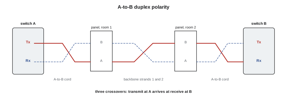
# Polarity check: count crossovers along a duplex path
def path(segments):
    side = "A"            # light leaves the transmitter in position A
    for name, crosses in segments:
        if crosses:
            side = "B" if side == "A" else "A"
        print(f"  after {name:28s} light is in position {side}")
    return side
good = [("A-to-B cord, switch A", True), ("backbone strands 1-2", True), ("A-to-B cord, switch B", True)]
bad = [("A-to-B cord, switch A", True), ("backbone strands 1-2", True), ("straight-through cord", False)]
for label, segs in (("standard channel", good), ("with a straight cord", bad)):
    print(label)
    end = path(segs)
print(" arrives at", "receive (link works)" if end == "B" else "transmit (no link)")standard channel after A-to-B cord, switch A light is in position B after backbone strands 1-2 light is in position A after A-to-B cord, switch B light is in position B arrives at receive (link works) with a straight cord after A-to-B cord, switch A light is in position B after backbone strands 1-2 light is in position A after straight-through cord light is in position A arrives at transmit (no link)
Polarity errors are found by looking for light, not by measuring loss. A visual fault locator, a red laser in a pen-sized tool, or a polarity tester sends visible light into a strand at one end so a technician at the other end can see which port it arrives at. Many certification testers also report polarity as part of their duplex loss test. Hollis checks polarity on every duplex link during testing, because the cost of finding it later is a technician on a ladder in front of a dead switch.
MPO polarity, briefly
MPO trunks carry 12 or more strands in one connector, and polarity across them is managed by three methods that TIA-568.3 names A, B and C. They differ in how the strands are arranged inside the trunk and which cassettes and cords are used at the ends. On a pre-terminated system like St. Brendan's, the manufacturer designs the polarity method and the installer's job is to use exactly the trunk, cassette and cord types the design names, in the orientation it shows. Mixing components from different polarity methods is the most common MPO installation error, and it is found the same way as duplex errors: by looking for light at the far end.
Worked problem
Choosing a connector for the Riverside pigtails
Sanjay's Riverside design calls for singlemode pigtails spliced to the 24-strand cable in each enclosure, connecting to the school board's switches. The switches' long-reach transceivers have duplex LC UPC ports. What connector and polish should the pigtails have, and what colour are they?
Show solution
- The switch ports are LC, so LC connectors avoid hybrid adapters.
- The transceivers are UPC; APC cords would not mate with them, so the patch side should be UPC. The pigtails and adapters in the enclosure follow the same polish.
- Singlemode UPC connectors and adapters are blue.
Answer: LC UPC singlemode pigtails, blue, in blue duplex LC adapters, with LC UPC A-to-B patch cords to the switches.
Checking connectors on delivery and in use
Connectors and cords are checked when they arrive and again before they are used. Hollis's crew opens a sample of each delivery of pigtails and patch cords, confirms the connector type, polish and fibre type against the order, and inspects a few end faces. A box of APC pigtails delivered in place of UPC is far easier to catch on the loading dock than in a tray. Cords that have been used, especially test cords, are inspected before every session, and any cord with a chipped or pitted end face is cut in half and thrown away, so that nobody picks it up again by mistake.
Visual fault locators are useful for a quick check of connectors and short cords too. The red light shines out of any break, crack or tight bend in a cord's jacket, and a damaged ferrule glows at its tip. Teo checks every cord in the crew's patch cord bag this way at the start of the season and finds two with cracked fibre just behind the boot, both from being stepped on in the truck.
Common mistakes
MistakeMating an APC connector with a UPC connector.
InsteadMatch polish types; green is APC, blue is singlemode UPC.
MistakeAssuming a link with good loss will work.
InsteadCheck polarity too: transmit must reach receive.
MistakeMounting duplex adapters in different orientations in different panels.
InsteadMount them the same way up everywhere, as the design shows.
MistakeMixing MPO trunks, cassettes and cords from different polarity methods.
InsteadUse exactly the components the design names, in the orientation it shows.
MistakeForcing a connector that does not seat.
InsteadCheck the type, polish and orientation before pushing harder.
Summary and key terms
- Connectors hold fibres in ceramic ferrules that are aligned by a split sleeve in the adapter and pressed together by springs.
- LC, with a 1.25 mm ferrule, is the standard duplex connector; SC and ST use 2.5 mm ferrules; MPO carries many fibres in one ferrule.
- UPC end faces are flat to the axis; APC faces are angled at 8° and are green; the two must never be mated.
- Reflectance measures light reflected back from a connection; more negative is better.
- The design budget allows 0.75 dB per mated pair; good connectors are well below that.
- Polarity ensures each transmitter reaches a receiver; duplex systems use A-to-B cords and an odd number of crossovers.
- MPO polarity methods are set by the design; the installer uses exactly the components it names.
- Ferrule
- The precision ceramic cylinder that holds and centres the fibre in a connector.
- Physical contact
- A connector design in which the fibre end faces are pressed together.
- APC
- Angled physical contact: an end face polished at 8° to reduce reflection.
- Reflectance
- The ratio of reflected to incident light at a connection, in negative dB.
- Adapter
- A coupling that aligns two connectors face to face.
- Polarity
- The arrangement that connects each transmitter to the receiver at the far end.
- A-to-B cord
- A duplex patch cord that crosses position A at one end to position B at the other.
Practice problems
Work each problem on paper first, then reveal the answer to check.
What colour is a singlemode APC connector?
Show answer
Green.
A connection reflects −30 dB. Is that good?
Show answer
No; that suggests dirt, damage or a gap. A clean UPC connection is about −50 dB or better.
Why does APC reduce reflection?
Show answer
The angled face sends reflected light into the cladding instead of back toward the source.
A channel has three crossovers. Does transmit reach receive?
Show answer
Yes; an odd number of crossovers takes position A to position B.
Lesson quiz · 5 questions
Score 60% or more to complete this lesson.
Create a free account to save your progress, take quizzes and earn a certificate.