
LVT-210 · Lesson 5 of 12 · 20 min
Fibre management: enclosures, panels and splice trays
A fibre cable that arrives in a telecommunications room still has a long way to go before it is a working link. The strands have to be separated from the cable, routed without stress to splice trays or connectors, protected and organised so that any one of them can be found and worked on years later without disturbing the others. This is fibre management, and it is where most of the difference between a neat installation and a troublesome one is decided. Hollis says she can tell how a site will test by opening its enclosures.
This lesson follows the preparation of the Riverside enclosures in the main building's room 1A and in the gymnasium, and the Kellerman backbone enclosures in the entrance room and room 6A. It covers the hardware, the colour code that identifies each strand, the routing rules inside the enclosure and the records that go with it.
Enclosures, panels and cassettes
A fibre enclosure, sometimes called a patch panel housing or a fibre distribution unit, is a box mounted in a rack or on a wall that holds the cable end, the splice trays and the adapter panels where patch cords connect. Rack-mounted enclosures come in heights of one to four rack units and hold 12 to 144 or more ports. Wall-mounted enclosures are used where there is no rack, such as the Hartwell warehouse's far end. Every enclosure provides four things: a secure clamp for the cable and its strength members, a route for the strands at more than the minimum bend radius, space for splice trays and slack, and adapter panels on the front.
Adapter panels are flat plates with a row of adapters, the sleeves that hold two connectors face to face. A typical panel holds six or twelve duplex LC adapters, or six to twelve SC adapters. Modular cassettes are a factory-assembled alternative: a closed module with an MPO connector on the back and LC adapters on the front, used with pre-terminated trunks such as those at St. Brendan's. LVT-120 covered the choice between these approaches; on site, the installer's job is to mount, route and label them correctly.
| Component | Purpose | Used at |
|---|---|---|
| Rack-mount enclosure | Holds cable ends, trays and adapter panels in a rack | Riverside 1A and gym, Kellerman ER1 and 6A |
| Wall-mount enclosure | Same functions where there is no rack | Hartwell far end, Juniper Point riser |
| Adapter panel | Front plate of adapters for patch cords | All enclosures |
| Splice tray | Holds and protects fusion splices and their slack | Riverside, Kellerman, Hartwell |
| MPO cassette | Breaks a pre-terminated trunk out to LC adapters | St. Brendan's data room |
| Fan-out kit | Adds 900 µm tubing to loose-tube fibres so they can be routed and connectorized | Occasional repairs |
Securing the cable
The cable is clamped at the back of the enclosure so that no pull on the cable outside can reach the strands inside. The jacket is cut back to the length the enclosure's instructions give, the aramid yarn is trimmed and clamped to the enclosure's strain relief, and the central strength member of a loose-tube cable is clamped to its post. A cable that is held only by a cable tie around its jacket can slide, and when it slides the strands inside are pulled tight around the tray edges.
With loose-tube cable, the buffer tubes are routed from the cable clamp to the splice trays. Gel-filled tubes are cleaned with a gel cleaner and lint-free wipes; dry tubes need only to be opened. The tubes are cut back at the tray entry, and the bare 250 µm fibres continue inside the tray. Where the tubes cross open space between the clamp and the tray, they are protected with transport tubing so they are not snagged or kinked.
The colour code
Every strand in a cable is identified by colour. The standard sequence, used in North America and set out in TIA-598, has twelve colours. In a loose-tube cable, the tubes are coloured in the same sequence, and the fibres inside each tube are coloured in the same sequence again, so fibre 14 is the second fibre, orange, in the second tube, also orange. Above twelve tubes or twelve fibres per tube, the sequence repeats with a stripe or a dash mark. Tight-buffered cables colour each 900 µm buffer the same way.
# TIA-598 sequence: fibre number to tube and strand position
SEQ = ["blue", "orange", "green", "brown", "slate", "white",
       "red", "black", "yellow", "violet", "rose", "aqua"]
PER_TUBE = 6
def identify(n, per_tube=PER_TUBE):
    tube, pos = divmod(n - 1, per_tube)
    tube_name = SEQ[tube % 12] + (" with stripe" if tube >= 12 else "")
    return tube + 1, tube_name, pos + 1, SEQ[pos % 12]
for n in (1, 6, 7, 14, 24):
    t, tn, p, pn = identify(n)
    print(f"strand {n:2d}: tube {t} ({tn}), position {p} ({pn})")
print()
print("Riverside 24F OS2, two tubes of 12:")
for n in range(1, 25, 6):
    t, tn, p, pn = identify(n, 12)
print(f" strand {n:2d} -> {tn} tube, {pn}")strand 1: tube 1 (blue), position 1 (blue) strand 6: tube 1 (blue), position 6 (white) strand 7: tube 2 (orange), position 1 (blue) strand 14: tube 3 (green), position 2 (orange) strand 24: tube 4 (brown), position 6 (white) Riverside 24F OS2, two tubes of 12: strand 1 -> blue tube, blue strand 7 -> blue tube, red strand 13 -> orange tube, blue strand 19 -> orange tube, red
The first run of the code uses six fibres per tube, the construction of the Kellerman tight-buffered subunits, where strand 14 is the second fibre in the third subunit. The second run uses the Riverside cable's twelve fibres per tube. Getting the colour order right matters because the splice on one end and the splice on the other end must join the same strands to the same ports. A pair of strands reversed in one tray shows up as two links that do not work and one very confused technician later.
Inside the splice tray
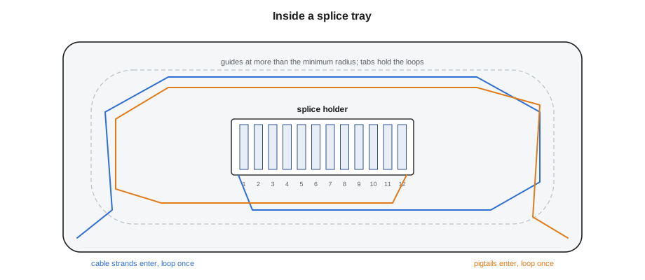
A splice tray is a shallow plastic or metal tray with a holder for the splice protectors in the middle and a route around the outside for slack fibre. Each tray holds a fixed number of splices, commonly 12 or 24. The fibre from the cable enters at one end, loops around the tray once or twice to store about a metre of slack, and reaches the splice holder. The pigtail fibre, which carries the connector to the front panel, enters from the other side, loops around and reaches the same holder. The slack is what allows a splice to be remade: the fibre is unwound, re-cleaved and re-spliced without running out of length.
The rules inside the tray are simple. The fibre never bends tighter than the tray's moulded guides, which are designed for the minimum radius of bare fibre, typically about 30 mm (1.2 in). The fibre is held under the tray's retaining tabs, never taped down hard or pinched under a lid. Tubes enter at the tray's entry points and are tied there. Each tray holds the strands of one tube, or a set the design calls for, so the colour sequence is easy to follow. The lid goes on without pressing on any fibre.
import math
# Enclosure planning: trays, ports and slack for each end of the Riverside route
strands = {"24F OS2": 24, "12F OM4": 12}
TRAY = 12              # splices per tray
PORTS_PER_PANEL = 12   # duplex LC panel = 12 strands
SLACK_PER_STRAND = 1.0  # stored in the tray, m
trays = sum(math.ceil(n / TRAY) for n in strands.values())
panels = sum(math.ceil(n / PORTS_PER_PANEL) for n in strands.values())
total = sum(strands.values())
print(f"strands per end: {total}")
print(f"splice trays per end: {trays}, adapter panels per end: {panels}")
print(f"fibre slack stored per end: {total * SLACK_PER_STRAND * 2:.0f} m (cable side and pigtail side)")
# A 2U enclosure takes 4 panels and 6 trays
print("fits a 2U enclosure:", panels <= 4 and trays <= 6)strands per end: 36 splice trays per end: 3, adapter panels per end: 3 fibre slack stored per end: 72 m (cable side and pigtail side) fits a 2U enclosure: True
Routing jumpers and front-of-panel management
On the front of the enclosure, patch cords run from the adapter panels to the switches. The same principles apply as for copper patching in LVT-130, with one addition: fibre cords are thinner and more easily bent past their limit. Cords are routed through the enclosure's front cord managers and the rack's vertical managers, never hung straight down across other ports, and never pulled tight across the front of a panel. Slack in cords is stored in the managers at a radius larger than the minimum. Cords that are too long are replaced with shorter ones rather than coiled tightly in front of the panel.
Dust caps stay on every adapter port and every connector that is not in use. A port that has had its cap removed and left open for a day in a room under construction is a port that will need cleaning and inspection before use. The crew keeps the caps on until the moment of connection, and replaces them on any port that is disconnected.
Labels and records for fibre
Fibre labelling follows the same TIA-606 scheme as copper, which LVT-120 covered. Each enclosure has an identifier, each adapter panel and port has a position, and each cable has an identifier that names both ends. On the Riverside route, the cable from room 1A to the gymnasium room G1 is labelled 1A-G1-SM24 and 1A-G1-OM12, and the ports in each enclosure are numbered 1 to 24 for the singlemode and 1 to 12 for the multimode, with the strand number matching the port number at both ends.
The fibre records add a splice map for each enclosure: which strand of which tube goes to which tray and splice position, and which pigtail goes from that position to which port. Hollis's crew fills in the map as they splice, and Maya checks it against the colour code before the lid goes on. The splice map is what lets a technician in five years find strand 14 without opening every tray.
| Port | Strand | Tube | Fibre colour | Tray, position |
|---|---|---|---|---|
| 1 | 1 | Blue | Blue | 1, 1 |
| 2 | 2 | Blue | Orange | 1, 2 |
| 12 | 12 | Blue | Aqua | 1, 12 |
| 13 | 13 | Orange | Blue | 2, 1 |
| 14 | 14 | Orange | Orange | 2, 2 |
| 24 | 24 | Orange | Aqua | 2, 12 |
Worked problem
Planning the Kellerman entrance room enclosure
The Kellerman backbone is a 24-strand singlemode tight-buffered cable made up of four subunits of six fibres. It will be spliced to LC pigtails in a 1U enclosure that holds two adapter panels of 12 strands and two splice trays of 12. Does it fit, and how are the subunits assigned?
Show solution
- 24 strands need two adapter panels of 12 and two trays of 12: the 1U enclosure has exactly that.
- Subunits 1 and 2 (blue and orange, strands 1 to 12) go to tray 1 and panel 1.
- Subunits 3 and 4 (green and brown, strands 13 to 24) go to tray 2 and panel 2.
- Strand 14 is the second fibre, orange, in the green subunit, in tray 2, position 2, port 14.
Answer: The enclosure fits with no spare capacity; Sanjay's design allows it because a second backbone would get its own enclosure.
Planning enclosure capacity for the future
An enclosure that is exactly full on the day it is installed is a problem for the next technician. Sanjay's designs leave room for growth wherever the rack allows: the Riverside enclosures are 2U units with space for four adapter panels and six splice trays, and the 24 OS2 and 12 OM4 strands use three panels and three trays at each end. The empty panel position and trays are for a second cable, if the board ever adds a building on the same route. At the Kellerman entrance room, where rack space is tight, the 1U enclosure is full, and the design notes say a second backbone gets its own enclosure.
Capacity also means slack. Every enclosure has a slack storage area for the cable's buffer tubes or subunits, and the routes between the cable clamp and the trays are long enough to move a tray out for work without pulling on the fibres. Hollis checks that each tray can be lifted out and laid on the work surface with its fibres still relaxed before she signs off an enclosure. If it cannot, the next technician will be tempted to work on it in place, at an awkward angle, with the risk of breaking a live strand.
Common mistakes
MistakeHolding the cable in the enclosure with a cable tie around the jacket.
InsteadClamp the strength members to the strain relief.
MistakeRouting bare fibre around a tight corner in the tray.
InsteadFollow the tray's moulded guides, which are designed for the minimum radius.
MistakeMixing tubes in a tray without a plan.
InsteadAssign one tube or a planned set of strands to each tray and record it in the splice map.
MistakeRemoving dust caps early to save time later.
InsteadKeep caps on until the moment of connection.
MistakeCoiling a long cord tightly in front of the panel.
InsteadRoute it through the managers at a safe radius or use a shorter cord.
Summary and key terms
- Enclosures hold the cable end, splice trays and adapter panels, and secure the cable by its strength members.
- The TIA-598 colour code identifies tubes and strands in a twelve-colour sequence.
- Splice trays store fibre slack in loops and hold splice protectors in numbered positions.
- Bare fibre follows the tray guides at more than its minimum bend radius and is never pinched.
- Front cords are routed through managers and kept capped when not connected.
- Labels follow TIA-606, and a splice map records every strand from tube to tray to port.
- Fibre enclosure
- A rack- or wall-mounted housing for cable ends, splice trays and adapter panels.
- Adapter panel
- A plate of adapters that join connectors face to face.
- Splice tray
- A tray that holds splice protectors and stores fibre slack in loops.
- Pigtail
- A short fibre with a factory connector on one end, spliced to the cable fibre.
- TIA-598 colour code
- The twelve-colour sequence used to identify tubes and strands.
- Splice map
- A record of which strand is spliced in which tray position and connected to which port.
Practice problems
Work each problem on paper first, then reveal the answer to check.
What colour is strand 9 in a twelve-fibre tube?
Show answer
Yellow.
In a cable with twelve fibres per tube, which tube and colour is strand 18?
Show answer
The orange tube, sixth position, white.
Why is slack stored in the splice tray?
Show answer
So the splice can be remade without running out of fibre.
What should happen to an adapter port that is not in use?
Show answer
It stays capped.
Lesson quiz · 5 questions
Score 60% or more to complete this lesson.
Create a free account to save your progress, take quizzes and earn a certificate.