
LVT-210 · Lesson 1 of 12 · 22 min
How optical fibre carries light
Maya's first two terms at Cobalt Line Systems were spent with copper: pulling, dressing, terminating and certifying four-pair cable on the Kellerman Building's sixth floor. In her fourth term she moves to the fibre crew. The crew is led by Hollis Tran, a journeyperson who has spliced and tested fibre for nineteen years, from campus backbones and hospital risers to the long outdoor routes between buildings. Hollis's first rule for apprentices is that nobody touches a cleaver or a fusion splicer until they understand what is happening inside the glass, because every installation practice in this course follows from it.
This course follows the fibre crew's work through one season. The first three lessons cover how fibre works, the fibre and cable types and the safety rules. Lessons 4 to 9 follow the installation: pulling cable, managing it in enclosures, connectors, field termination, fusion splicing, and cleaning and inspection. Lessons 10 and 11 cover the two tiers of testing: loss testing with a light source and power meter, and OTDR testing. The capstone builds and certifies the Riverside school's campus backbone between the main building and the gymnasium, the route that LVT-120 designed. LVT-120 lesson 8 introduced fibre in the structured cabling system; this course turns that overview into hands-on work.
Why fibre
Copper carries a signal as voltage and current on a pair of conductors. Fibre carries it as pulses of light in a strand of glass about the thickness of a human hair. Light in glass loses very little energy over distance and is not affected by electrical noise, lightning, ground potential differences or the power cables running beside it. A singlemode link can carry data tens of kilometres without amplification, where a copper channel is limited to 100 m (328 ft). That is why backbones between rooms and buildings are almost always fibre, and why the horizontal copper on a floor ends at a room that the fibre connects to the rest of the building.
Fibre also weighs less, takes less space and carries no electrical energy. A 24-strand singlemode cable is smaller than a single Category 6A cable and can carry more traffic than the whole floor of copper it serves. The cost is that glass is less forgiving of poor workmanship. A copper jack that is slightly untwisted still works and shows up as a reduced margin. A fibre end face with a speck of dust on the core, or a cable bent too tightly around a corner, can lose most of the light.
- Bandwidth: one fibre pair can carry 10, 40, 100 Gb/s and more, depending on the electronics at the ends.
- Distance: multimode links reach hundreds of metres; singlemode links reach many kilometres.
- Immunity: no electromagnetic interference, no ground loops and no lightning paths between buildings when the cable is dielectric.
- Size and weight: high strand counts in small cables, and less load on trays and supports.
- Security: fibre does not radiate a signal that can be picked up nearby.
Light as a signal
A transmitter converts the electrical data signal into light. In short-reach multimode systems, the source is usually a vertical-cavity surface-emitting laser, called a VCSEL, operating at 850 nm. In singlemode systems, the source is a laser at 1310 nm or 1550 nm. These wavelengths are infrared and invisible to the eye, a fact that matters for safety, as lesson 3 explains. At the far end, a photodiode converts the light back into an electrical signal.
The wavelengths are not chosen at random. Glass absorbs and scatters light differently at different wavelengths, and the losses are lowest in a few bands called windows. The 850 nm window is used for multimode because inexpensive sources work there. The 1310 nm and 1550 nm windows are where singlemode glass has its lowest loss, and 1550 nm is also where the fibre is most sensitive to bending, which installers use to their advantage when testing, as lessons 10 and 11 show.
Power in fibre systems is measured in decibels relative to one milliwatt, written dBm. Zero dBm is one milliwatt; minus 10 dBm is a tenth of a milliwatt; minus 20 dBm is a hundredth. A typical short-reach transmitter launches somewhere between −1 and −7 dBm, and a receiver might work down to about −10 to −14 dBm. Loss in a link is measured in plain decibels, dB, because it is a ratio. Every 3 dB of loss halves the power; 10 dB leaves a tenth of it.
Inside the strand: core, cladding and coating
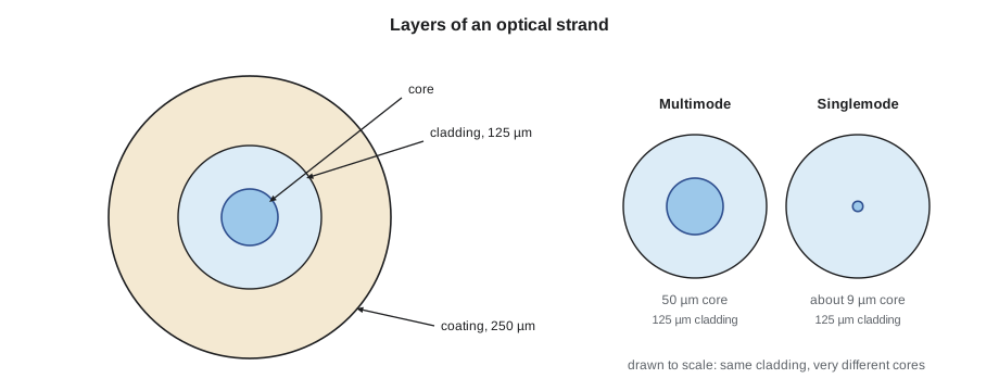
An optical fibre has three layers. The core, at the centre, carries the light. Around it is the cladding, also glass, with a slightly lower refractive index. Together, the core and cladding are 125 µm in diameter for almost every telecommunications fibre. Around the cladding is a protective acrylate coating, usually 250 µm in diameter, or 200 µm in some reduced-coating fibres used in high-count cables. The coating protects the glass from scratches and moisture; it is stripped off before cleaving and splicing.
The core diameter decides the fibre type. Multimode fibre has a core of 50 µm in all modern grades, or 62.5 µm in older installations. Singlemode fibre has a core of about 8 to 9 µm. That difference, roughly six times in diameter and thirty times in area, explains most of the difference in how the two types are handled. A tiny misalignment at a singlemode connector or splice that would barely matter in multimode can cost a large fraction of the light.
Refraction and total internal reflection
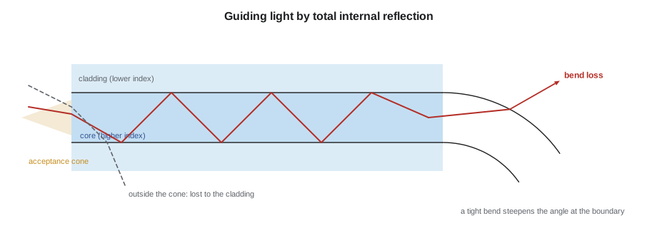
Light travels more slowly in glass than in air. The ratio of the speed of light in a vacuum to its speed in a material is the refractive index, n. Air is about 1.000, and the glass in a fibre core is about 1.47 to 1.48. When light crosses a boundary between two materials at an angle, it bends; this is refraction, described by Snell's law. If light inside a material with a high index meets a boundary with a material of lower index at a shallow enough angle, it does not cross at all: it is reflected entirely back. This is total internal reflection, and it is what keeps light in the core.
The core of a fibre has a slightly higher refractive index than the cladding, typically by about one percent or less. Light that enters the core within a certain cone of angles strikes the core-cladding boundary at a shallow enough angle to be reflected each time, and is guided along the fibre. Light that enters outside the cone passes into the cladding and is lost. The half-angle of that cone is the acceptance angle, and the sine of it is the numerical aperture, NA.
Here n₁ is the refractive index of the core and n₂ that of the cladding. Multimode fibre has an NA of about 0.20, singlemode about 0.12 to 0.14. A larger NA means the fibre accepts light from a wider cone, which is why multimode fibre can be used with cheaper, less precisely aimed sources. The code below calculates the critical angle, the NA and the acceptance angle for representative indices, and the time light takes to travel along the Riverside campus route.
import math
# Critical angle, numerical aperture and acceptance angle for two fibre types
types = {"multimode (50 um core)": (1.4800, 1.4664),
         "singlemode (9 um core)": (1.4677, 1.4624)}
for name, (n1, n2) in types.items():
    crit = math.degrees(math.asin(n2 / n1))
    na = math.sqrt(n1**2 - n2**2)
    accept = math.degrees(math.asin(na))
    print(f"{name}: critical angle {crit:.1f} deg, NA {na:.3f}, acceptance half-angle {accept:.1f} deg")

# How long does light take to cross the campus route?
C = 299_792_458          # speed of light in a vacuum, m/s
route = 320          # length, m
metres = route * 1
for n in (1.4677, 1.4800):
    t_us = metres * n / C * 1e6
print(f"group index {n}: {route} m in {t_us:.2f} microseconds")multimode (50 um core): critical angle 82.2 deg, NA 0.200, acceptance half-angle 11.5 deg singlemode (9 um core): critical angle 85.1 deg, NA 0.125, acceptance half-angle 7.2 deg group index 1.4677: 320 m in 1.57 microseconds group index 1.48: 320 m in 1.58 microseconds
Light crosses the 320 m (1,050 ft) route in about one and a half microseconds. The figure matters later, because an OTDR measures distance by timing light pulses and converting the time to length with exactly this relationship. The critical angles also show how small the margin is: light must strike the boundary within a few degrees of grazing to stay in the core. A tight bend changes the angle of the boundary and lets light escape, which is the subject of the next section.
Modes, dispersion and why multimode reach is limited
In a large core, light can travel along many paths at once: straight down the middle, or zigzagging at different angles. Each allowed path is called a mode. A multimode fibre carries hundreds of modes; a singlemode fibre, with its tiny core, carries only one. Paths of different lengths take different times, so a short pulse launched into a multimode fibre arrives spread out. This is modal dispersion, and it is what limits how fast and how far a multimode link can run before one pulse blurs into the next.
Modern multimode fibre reduces modal dispersion with a graded-index core. Instead of a sharp step in refractive index at the core edge, the index is highest at the centre and falls gradually toward the cladding. Rays that travel the longer zigzag paths spend more time in the outer, lower-index glass where light moves faster, so they catch up with the rays travelling straight down the centre. The quality of that grading is what separates the OM grades of multimode fibre, described in lesson 2, and it is expressed as the fibre's modal bandwidth.
Singlemode fibre has no modal dispersion because it carries only one mode. Its limit is chromatic dispersion: different wavelengths in the source travel at slightly different speeds. Chromatic dispersion matters for long-haul links at high speeds, but for the distances in buildings and campuses, singlemode fibre has effectively unlimited bandwidth. That is the main reason designers like Sanjay specify singlemode for new backbones: the glass will not be the limit for any foreseeable upgrade.
| Property | Multimode | Singlemode |
|---|---|---|
| Core diameter | 50 µm (older 62.5 µm) | about 8 to 9 µm |
| Cladding diameter | 125 µm | 125 µm |
| Typical NA | about 0.20 | about 0.12 to 0.14 |
| Operating wavelengths | 850 nm and 1300 nm | 1310 nm and 1550 nm |
| Main bandwidth limit | Modal dispersion | Chromatic dispersion, rarely limiting in buildings |
| Typical sources | VCSELs, inexpensive | Lasers, more expensive |
| Typical use | Inside buildings and data centres, short links | Backbones, campuses, long links, new installations |
Where light is lost
Every link loses some light between the transmitter and the receiver. The installer's job is to keep that loss small and predictable. The causes fall into two groups: losses in the glass itself, which the installer cannot change, and losses at bends, connectors and splices, which are almost entirely the result of workmanship.
- Attenuation in the glass: absorption by impurities and scattering from tiny variations in the glass, measured in dB per kilometre. It is lowest at 1550 nm in singlemode fibre.
- Macrobending: a visible bend tighter than the fibre's rated radius, such as a cable pulled around a sharp corner or a strand coiled too tightly in a splice tray.
- Microbending: tiny distortions of the fibre axis from crushing, a tight cable tie, or a cable squeezed against an edge. It can add loss along a whole length.
- Connectors: light crossing a gap between two end faces, losing some from misalignment, dirt and reflection.
- Splices: two fibres fused or held together, with a small loss from core misalignment.
Bending loss is worse at longer wavelengths, because the light's field extends further into the cladding. A singlemode fibre that is bent slightly too tightly may show almost no extra loss at 1310 nm and a clear loss at 1550 nm. Testing at both wavelengths and comparing the results is the standard way to find bends, and Hollis checks that difference on every singlemode link she tests.
Bend-insensitive fibres, which the standards call bend-loss-reduced fibres, tolerate much tighter bends than older glass. Most new multimode and singlemode fibre installed in buildings is of this type. They are a real benefit in crowded enclosures and pathways, but they do not remove the mechanical bend radius limits of the cable itself, which protect the glass from breaking. Hollis tells her apprentices to treat every fibre as if it were the old, sensitive kind.
The fibre crew and the season ahead
Hollis's crew this season is three people: Hollis, Maya and a second-year apprentice, Teo Barros. Dev Malhotra, who mentored Maya through her first terms, now leads the copper work at St. Brendan's Hospital, and the fibre crew will meet him there. Sanjay Iyer designed most of the routes the crew will build, and Colette Brennan manages the projects and the schedule. Greta Lindqvist reviews every safety plan.
| Job | Fibre work | Lessons |
|---|---|---|
| Kellerman Building | 24-strand singlemode backbone from the entrance room to room 6A, terminated with splice-on pigtails | 2, 5, 6, 7 |
| Juniper Point condominium | Existing 12-strand OM3 riser, new enclosures and a live cut-over | 3, 9 |
| St. Brendan's Hospital | Pre-terminated MPO trunks in the new data room, and a diverse second riser | 6, 7, 10 |
| Hartwell warehouse | A fibre-fed wall enclosure at the far end of the building | 4, 8 |
| Riverside school | 24-strand singlemode and 12-strand OM4 campus route to the gymnasium | 4, 5, 8, 10, 11, 12 |
Worked problem
Power left at the receiver
A transmitter launches −3.0 dBm into a link with 2.4 dB of total loss. What power reaches the receiver, in dBm and in microwatts?
Show solution
- Received power in dBm is launch power minus loss: −3.0 − 2.4 = −5.4 dBm.
- Convert to milliwatts: P = 10 raised to the power of (−5.4 ÷ 10) = 0.288 mW.
- In microwatts that is about 288 µW.
Answer: The receiver sees about −5.4 dBm, or roughly 288 µW, a little more than half the launched 501 µW.
Common mistakes
MistakeTreating fibre like copper: if it lights up, it works.
InsteadA link can pass light and still exceed its loss budget; it must be measured.
MistakeAssuming bend-insensitive fibre can be bent without limit.
InsteadThe cable's bend radius still protects the glass and must be respected.
MistakeTesting singlemode at one wavelength only.
InsteadTest at 1310 nm and 1550 nm; a difference reveals bends.
MistakeAdding dBm values together.
InsteadAdd and subtract dB of loss from a power in dBm; two dBm powers are not added directly.
MistakeForgetting that the core is tiny.
InsteadSmall misalignments and specks of dirt matter, above all in singlemode.
Summary and key terms
- Fibre carries data as pulses of infrared light, with low loss, high bandwidth and no electrical interference.
- A fibre has a core, a cladding of 125 µm and a coating of 250 µm; multimode cores are 50 µm, singlemode about 9 µm.
- Total internal reflection keeps light inside the core when it enters within the acceptance cone, whose sine is the numerical aperture.
- Multimode fibre carries many modes and is limited by modal dispersion; graded-index cores reduce it.
- Singlemode fibre carries one mode and is not bandwidth-limited at building and campus distances.
- Light is lost in the glass, at bends, at connectors and at splices; bend loss is greater at longer wavelengths.
- Power is measured in dBm and loss in dB; every 3 dB halves the power.
- Core
- The central glass region of a fibre that carries the light.
- Cladding
- The glass layer around the core, with a lower refractive index, normally 125 µm in diameter.
- Refractive index
- The ratio of the speed of light in a vacuum to its speed in a material.
- Numerical aperture
- The sine of the acceptance half-angle; a measure of how wide a cone of light a fibre accepts.
- Mode
- One of the paths along which light can travel in a fibre.
- Modal dispersion
- Spreading of a pulse because different modes take different times to travel the fibre.
- dBm
- Optical power in decibels relative to one milliwatt.
- Macrobend
- A visible bend tighter than the rated radius, causing loss.
Practice problems
Work each problem on paper first, then reveal the answer to check.
A source launches −2 dBm into a link with 3 dB of loss. What arrives?
Show answer
−5 dBm, about half of the launched power.
A core has n = 1.470 and the cladding n = 1.455. What is the NA?
Show answer
√(1.470² − 1.455²) ≈ 0.209.
Why is singlemode chosen for most new backbones?
Show answer
Its bandwidth is not a limit at building and campus distances, so it will carry future upgrades.
A link shows 0.4 dB more loss at 1550 nm than at 1310 nm. What does that suggest?
Show answer
A bend somewhere in the link.
Lesson quiz · 5 questions
Score 60% or more to complete this lesson.
Create a free account to save your progress, take quizzes and earn a certificate.