
LVT-120 · Lesson 9 of 12 · 19 min
Pathways and spaces (TIA-569)
Cable needs a route, and the route has to be planned, built and protected as carefully as the cable itself. Pathways are the conduits, trays, hooks, sleeves and raceways that carry cable from room to outlet; spaces are the rooms and enclosures of Lesson 3. ANSI/TIA-569 covers both. Pathway problems are the most common reason a well-designed cabling system fails in practice: cable crushed in an overfilled conduit, stretched around too many bends, draped across ceiling tiles, tied to a sprinkler pipe or bundled so tightly that it overheats. This lesson covers the main pathway types, the rules that keep each one within its limits, and how Sanjay and Maya plan pathway capacity on a project.
Types of pathway
Inside a building, horizontal cabling uses one or more of five pathway types. Each suits different conditions.
- Conduit is a metal or rigid non-metallic tube. Electrical metallic tubing, abbreviated EMT, is the usual type indoors. Conduit gives the best protection and is required by some codes and owners in particular spaces, but it holds few cables, is slow to install and is hard to add to. It is used for drops in walls, through inaccessible spaces, under floors on grade and for backbone between rooms.
- Cable tray is a continuous open support: ladder tray with rungs, wire-basket tray made of welded wire, or solid-bottom tray. Tray carries large numbers of cables along corridors and into telecommunications rooms, and it is easy to add cable to. Wire basket is the most common type for horizontal cabling in ceilings.
- Non-continuous supports, usually J-hooks or cable hangers, hold cable at intervals from the structure above the ceiling. They are inexpensive and flexible and are the most common pathway for the branches from a tray to individual outlets, and in many smaller buildings for the whole route.
- Surface raceway is a metal or plastic channel fixed to the wall surface, used in renovations where cable cannot be concealed in walls.
- Underfloor and access floor pathways serve open areas away from walls: cellular floor ducts and in-floor trenches in older buildings, and the space under raised access floors in data centres and some offices.
Most projects combine them. At the Kellerman Building, a wire-basket tray runs along the main corridor ceiling from the telecommunications room, J-hooks carry branches from the tray to each office, and each cable drops to its outlet inside the wall through a low-voltage bracket or a short conduit stub from the box to above the ceiling.
Conduit rules
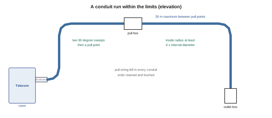
Pulling cable through conduit stretches it, and every bend multiplies the pulling tension. To keep the tension within the cable's rating, TIA-569 limits conduit runs between pull points: no more than 30 m (100 ft) of conduit, and no more than two 90 degree bends, 180 degrees in total, between pull boxes or other pull points. A pull box with an offset of the conduit through it does not count as a bend, but a box used to change direction must be large enough for the cable's bend radius.
The bends themselves must be gentle. For conduit of 50 mm (2 in) trade size or smaller, the inside radius of a bend should be at least six times the conduit's internal diameter; for larger conduit, at least ten times. Factory-made sweeps meet these radii; the short-radius elbows used for electrical wiring do not, and a conduit installed by the electrical trade with tight elbows is one of the most common coordination problems on a job. Every conduit should be left with a pull string or pull rope, every end reamed and bushed so that its edge does not cut the jacket, and every empty conduit capped until it is used.
Conduit fill is limited so that cables can be pulled without damage and later added or removed. The electrical code's tables allow 53 percent of the conduit's internal area for one cable, 31 percent for two and 40 percent for three or more, and TIA-569 uses the same 40 percent for planning. Many designers plan lower, for example to leave room for future cables or to reduce pulling tension in long runs.
# How many cables fit in a conduit at 40 % fill?
import math
cable_od = 7.4              # Category 6A outside diameter, mm
conduits = {"21 mm": 20.9, "27 mm": 26.6, "35 mm": 35.1, "41 mm": 40.9, "53 mm": 52.5}           # trade size: internal diameter (mm)
cable_area = math.pi * (cable_od / 2) ** 2
for size, inside in conduits.items():
    area = math.pi * (inside / 2) ** 2
    n = int(0.40 * area // cable_area)
print(f"{size:>8} conduit: internal area {area:7.0f} sq mm, {n:3d} cables at 40 % fill")21 mm conduit: internal area 343 sq mm, 3 cables at 40 % fill 27 mm conduit: internal area 556 sq mm, 5 cables at 40 % fill 35 mm conduit: internal area 968 sq mm, 8 cables at 40 % fill 41 mm conduit: internal area 1314 sq mm, 12 cables at 40 % fill 53 mm conduit: internal area 2165 sq mm, 20 cables at 40 % fill
The figures show why Category 6A, at about 7.4 mm (0.29 in) outside diameter, changed pathway design. A 27 mm (1 in) conduit, which might hold six or seven of the slimmer Category 5e cables, holds only five Category 6A cables. Owners who moved to Category 6A without enlarging their pathway standards found their conduits and trays full years early.
Cable tray and J-hooks
Cable tray and J-hooks carry most horizontal cable in ceilings. Both have rules for capacity and support.
Tray fill is limited so that cables at the bottom of the tray are not crushed by those above, and so that heat can escape. Designers commonly plan a tray for an initial fill of about 25 percent of its cross-sectional area, leaving room for growth, and do not let it exceed about 50 percent. Trays must be supported at the intervals the manufacturer specifies, must have clear access above them for adding cable, typically about 300 mm (12 in), and must be bonded where they are metallic. Where a tray turns a corner, drops into a room or ends, waterfalls or radius drop-outs keep cables from bending sharply over the edge.
J-hooks and other non-continuous supports must be close enough together that the cable does not sag excessively between them, and wide enough that the cable bears on a broad, smooth surface rather than a narrow edge. TIA-569 sets a maximum spacing of 1.5 m (5 ft). Many designers vary the spacing slightly, between about 1.2 and 1.5 m (4 and 5 ft), because perfectly uniform spacing can create a regular pattern of sag that slightly degrades return loss at certain frequencies. Sag between supports should be limited to about 300 mm (12 in). Each J-hook has a capacity, given by its manufacturer as a number of cables of a given diameter; bundles larger than the hook's rating are crushed at the bottom.
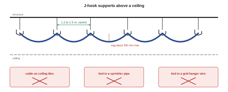
Some supports are never acceptable. Cable must not lie on ceiling tiles, which get moved, and on which cable is crushed and lost; must not be tied to the ceiling grid's hanger wires, which support only the ceiling; and must not be attached to sprinkler pipes, ducts, electrical conduit or other services. The electrical code itself forbids cables from being supported by the ceiling grid or its wires unless separate support wires are provided for them, and forbids cables from being installed in ways that prevent the removal of ceiling panels. Cables also need clearance from heat sources such as light fixtures and from power cables, covered with the code rules in LVT-330.
# J-hooks for a ceiling route: count, spacing and capacity
import math
route = 46.0                   # length of the branch from tray to the end office, m
max_spacing = 1.5             # TIA-569 maximum, m
spacing = 1.35                 # Cobalt Line's planned average, m
cables_on_route = 38           # at the start of the branch
hook_capacity = 25             # manufacturer: Category 6A cables per 2-inch hook

hooks = math.ceil(route / spacing) + 1
per_hook = math.ceil(cables_on_route / hook_capacity)
print(f"hooks along the route: {hooks} ({spacing} m average, {max_spacing} m maximum)")
print(f"{cables_on_route} cables need {per_hook} hooks side by side at each support point")
print(f"total hooks to order: {hooks * per_hook}, plus 10 % spares: {math.ceil(hooks * per_hook * 1.1)}")hooks along the route: 36 (1.35 m average, 1.5 m maximum) 38 cables need 2 hooks side by side at each support point total hooks to order: 72, plus 10 % spares: 80
Sleeves, slots and penetrations
Wherever a pathway passes through a wall or floor, it needs a sleeve or opening, and wherever that wall or floor has a fire rating, the opening must be firestopped. Sleeves through rated walls into telecommunications rooms are typically several 100 mm (4 in) sleeves above the ceiling, sized for the room's full future cable, and sleeves through floors are as described for the riser in Lesson 4. Many owners now specify pathway devices that are listed as firestops in themselves, with built-in intumescent seals that allow cables to be added without re-sealing. Penetrations of walls that are not rated still need sleeves or grommets to protect the cable. Cobalt Line photographs every penetration after firestopping, because inspectors and owners increasingly ask for the record.
Planning pathway capacity
Pathways are sized for the cable they will carry at the end of the building's life, not on opening day. Sanjay's method is to count the cables each section of pathway carries, using the outlet layout, add the cables for future outlets and devices, convert to area using the cable diameter, and then size the tray or conduit for that area at the planned fill. The main corridor tray at the Kellerman Building carries every cable from the telecommunications room to the far half of the floor, so it is the largest; branches shrink as cables peel off to rooms.
Ceiling space is shared, and the pathway must be coordinated with ducts, sprinklers, lighting, electrical conduit and structure. On larger projects this coordination happens in a three-dimensional building model, in which each trade's systems are modelled and clashes are found before installation. On smaller projects it happens on site, and Maya learns that the time to point out a tray route blocked by a new duct is before the duct is hung, not after.
Worked problem
A branch route at the Kellerman Building
From the corridor tray, a branch of 18 Category 6A cables runs 22 m (72 ft) through the ceiling to a row of four offices. The electrician's drawings show a 27 mm (1 in) conduit from the ceiling down to each office's outlet box. Each office has four cables. What should Maya check?
Show solution
- J-hooks: 22 m (72 ft) at about 1.35 m (4.4 ft) spacing needs about 18 hooks; 18 cables fit in one hook rated for 25.
- Conduit drops: a 27 mm (1 in) conduit holds five Category 6A cables at 40 percent fill, so four cables per office fit with room for one more.
- Bends: each drop has one sweep from horizontal to vertical, and its length is well under the limit, so no pull box is needed.
- Support: the hooks attach to the structure, not to the ceiling grid wires, and the route stays clear of the sprinkler branch lines shown on the coordination drawing.
Answer: The branch and drops are within the limits; Maya marks the hook locations on the structure and confirms clearance from the sprinkler lines before installation.
Pathways also need access for the life of the building. Tray and hooks above an accessible ceiling can be reached by lifting tiles; those above drywall ceilings need access panels at pull points, junctions and zone boxes, which the drawings must show. A pathway that cannot be reached cannot be added to, and the building's next tenant will pay for that.
Common mistakes
MistakeAccepting short-radius electrical elbows in a telecommunications conduit.
InsteadUse sweeps with an inside radius of at least six times the conduit's internal diameter.
MistakePutting three 90 degree bends between pull points.
InsteadInstall a pull box after two bends.
MistakeFilling conduit to the code maximum on day one.
InsteadPlan for growth; fill limits are maximums.
MistakeLaying cable on ceiling tiles or tying it to grid wires or sprinkler pipes.
InsteadSupport cable from the structure on its own hooks, tray or support wires.
MistakeLeaving a penetration unsealed after adding cable.
InsteadRestore the firestop every time, and record it.
Summary and key terms
- Pathways include conduit, cable tray, J-hooks and other non-continuous supports, surface raceway and underfloor systems.
- Conduit runs are limited to 30 m (100 ft) and two 90 degree bends between pull points, with bend radii of at least six times the internal diameter for small conduit.
- Conduit fill is planned at no more than 40 percent for three or more cables; Category 6A fills pathways faster than older categories.
- Trays are planned at about 25 percent initial fill and no more than about 50 percent; J-hooks are spaced at no more than 1.5 m (5 ft) with limited sag.
- Cable must never rest on ceiling tiles or be supported by grid wires, pipes or other services.
- Penetrations of rated walls and floors are sleeved and firestopped, and pathways are sized for the building's future cable.
- Pathway
- A facility for carrying cable, such as conduit, tray or J-hooks.
- EMT
- Electrical metallic tubing, the common thin-wall metal conduit used indoors.
- Pull box
- A box in a conduit run that provides access for pulling cable.
- Sweep
- A conduit bend with a large radius suitable for communications cable.
- Fill
- The percentage of a pathway's cross-sectional area occupied by cable.
- J-hook
- A non-continuous cable support attached to the structure.
- Waterfall
- A curved fitting that supports cables where they drop off the edge of a tray.
- Firestop
- A listed system that restores the fire rating of a wall or floor around a penetration.
Practice problems
Work each problem on paper first, then reveal the answer to check.
A conduit run needs three 90 degree bends. What must be added?
Show answer
A pull box (or other pull point) so that no section has more than two bends.
What is the minimum inside bend radius for a 35 mm conduit with a 35.1 mm internal diameter?
Show answer
6 × 35.1 = about 211 mm.
How many J-hooks support a 30 m route at 1.4 m spacing, counting both ends?
Show answer
30 / 1.4 = 21.4, so 22 spaces, 23 hooks.
Why should J-hook spacing vary slightly?
Show answer
Uniform spacing can create a periodic sag pattern that degrades return loss at certain frequencies.
Lesson quiz · 5 questions
Score 60% or more to complete this lesson.
Create a free account to save your progress, take quizzes and earn a certificate.