
LVT-120 · Lesson 3 of 12 · 21 min
Entrance facilities, equipment rooms and telecommunications rooms
Cabling is only as good as the rooms it connects. A telecommunications room that is too small, too hot, shared with a mop sink or placed at the far end of a floor will cause problems for the life of the building, and very little can be done about it once the walls are built. The rooms are defined in ANSI/TIA-569, the pathways and spaces standard, with design guidance in BICSI's manuals. They are drawn by architects, often early in design and often without a telecommunications designer at the table, which is why Sanjay spends much of his time on new projects reviewing room locations and sizes before anyone has thought about cable. This lesson walks through the three kinds of space in order: the entrance facility, the equipment room and the telecommunications room, with the small telecommunications enclosure as a fourth.
The entrance facility
The entrance facility is where cables from outside the building come in. It usually holds the service providers' cables, the campus backbone cables from other buildings and sometimes antenna cables, and it contains the demarcation point, where the service provider's network ends and the owner's begins. Service providers usually install their own termination equipment at the demarcation point, and Cobalt Line's work begins on the owner's side of it.
Underground entrances arrive through conduits, often several 100 mm (4 in) conduits laid from a property-line maintenance hole or handhole, with at least one spare for a future provider. Each conduit should be sealed where it enters the building against water and gas. Metallic cables entering from outside, such as copper telephone cable, must be fitted with primary protectors near the point of entry, which carry lightning and power-contact surges to ground before they reach the building's cabling. The electrical code also limits how far an outside cable that is not rated for indoor use may run inside the building before it must be terminated or enclosed, typically 15 m (50 ft). Optical fibre cables with no metallic parts need no protector, but those with a metallic strength member or armour must have it bonded. The details of bonding and protection are the subject of LVT-330.
The entrance facility may be a separate room, a wall area in the equipment room or, in a small building, a backboard in the telecommunications room. In larger buildings it is kept separate so that service provider technicians can work there without access to the owner's equipment.
The equipment room
The equipment room is the centre of the building's network. It houses the main cross-connect, the core switches and routers, often the telephone system and servers, and in many buildings the head-end equipment of other low-voltage systems such as video recorders and access control servers. Because everything depends on it, the equipment room has the strictest requirements of any space in the system.
- Size. A long-standing planning figure gives about 0.07 m² (0.75 ft²) of equipment room floor space for every 10 m² (100 ft²) of usable workstation area, with a minimum of about 14 m² (150 ft²). Equipment-heavy buildings such as hospitals and data-intensive offices are sized from the actual racks and cabinets instead.
- Location. Central to the building to keep backbone runs short, away from sources of electromagnetic interference such as transformers and large motors, away from water such as washrooms and roof drains, and above any flood level, never in a basement prone to flooding.
- Environment. Continuous cooling, independent of the building's normal schedule, to keep the room within the temperature range the equipment manufacturer recommends, typically about 18 to 27 °C (64 to 81 °F) at the equipment intakes, with humidity control.
- Power. Dedicated circuits for the equipment, typically at least two per rack, fed from emergency power where the building has it and backed by an uninterruptible power supply; separate, normal circuits for lighting and convenience outlets.
- Access. A door of at least 910 mm (36 in) wide and 2,130 mm (84 in) high, without a sill, opening outward, locked and usually on the card access system. The room should contain nothing that does not belong to it: no electrical panels for other areas, no plumbing, no storage.
In smaller buildings the equipment room and a telecommunications room are often combined. That is acceptable as long as the combined space meets the requirements of both.
The telecommunications room
Each floor needs at least one telecommunications room. TIA-569 calls for additional rooms when the floor area served is larger than about 1,000 m² (10,000 ft²), and whenever the horizontal distance from the room to any outlet would exceed 90 m (295 ft) of cable. That 90 m limit is measured along the cable route, through the ceiling and down the walls, not in a straight line on the floor plan, and Lesson 5 shows how quickly a route consumes it. On multi-storey buildings, the telecommunications rooms should be stacked vertically, one above the other, so that the backbone can run straight up through sleeves or slots in each floor.
Room size depends on the area served and the equipment it holds. A design rule from earlier editions of TIA-569, still widely used, sizes the room at about 3 m by 3.4 m (10 ft by 11 ft) to serve 1,000 m² (10,000 ft²) of floor, with smaller rooms for smaller areas. Current practice sizes the room from the number of racks it must hold and the clearances around them. A two-rack room needs space for the racks, about 1 m (3 ft) of clear working space in front of and behind them, cable management on each side, a wall backboard for wall-mounted equipment and room for the ladder rack overhead.
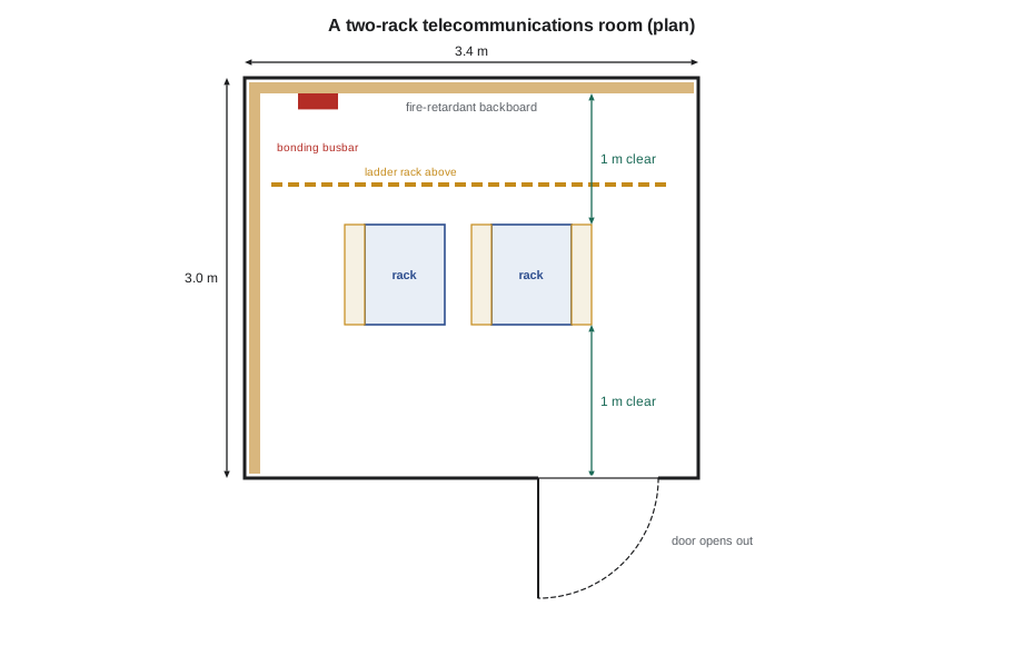
The room's walls are usually lined with a backboard of fire-retardant plywood, about 19 mm (3/4 in) thick and 2.4 m (8 ft) high, painted with fire-retardant paint that leaves the fire-rating stamp visible for the inspector. The backboard carries wall-mounted equipment such as small panels, power supplies and protection blocks. Overhead, a ladder rack or cable runway carries cables from the entry sleeves to the tops of the racks.
The other requirements echo those of the equipment room on a smaller scale: dedicated power with at least two circuits per rack, cooling that runs around the clock because the switches run around the clock, lighting of about 500 lux measured at the front of the racks, a card-controlled door, and nothing stored that does not belong. A telecommunications room is not a janitor's closet, an electrical room or a storage room, and sharing it with any of these is a common design error that Sanjay flags on architectural drawings.
Racks and rack units
Equipment in telecommunications rooms is mounted in 19-inch racks or cabinets. The name refers to the width of the mounting rails, 482.6 mm (19 in), a dimension set by the EIA-310 standard and used worldwide, even on metric projects. Height is measured in rack units, abbreviated U, of 44.45 mm (1.75 in) each. A standard floor-standing rack has 42 or 45 usable units. Patch panels typically take 1 U for 24 ports or 2 U for 48; a 48-port switch takes 1 U; horizontal cable managers, placed between panels and switches, take 1 or 2 U each. Two-post open racks are common in telecommunications rooms; four-post racks and enclosed cabinets are used for heavy equipment and in equipment rooms.
Sanjay sizes a room by laying out the rack elevations: each panel, manager and switch drawn in its position. His script below does the arithmetic for a floor: from the number of outlets it finds the patch panels and switches needed, adds managers and spare space, and reports how many racks the room must hold.
# How many racks does a telecommunications room need? (interconnect layout)
import math
outlets = 380            # horizontal cables ending in this room
backbone_u = 4           # fibre and copper backbone panels
ups_u = 3                # rack-mounted UPS
rack_u = 42              # usable units per rack
growth = 0.25            # space reserved for growth

panels = math.ceil(outlets / 48)           # 48-port, 2 U panels
switches = math.ceil(outlets / 48)         # 48-port, 1 U switches
managers = panels + switches               # 1 U horizontal manager above each item
used_u = panels * 2 + switches * 1 + managers * 1 + backbone_u + ups_u
needed_u = used_u * (1 + growth)
racks = math.ceil(needed_u / rack_u)
print(f"patch panels: {panels} (2 U each), switches: {switches}, managers: {managers}")
print(f"units used now: {used_u} U; with {growth:.0%} growth: {needed_u:.0f} U")
print(f"racks of {rack_u} U required: {racks}")patch panels: 8 (2 U each), switches: 8, managers: 16 units used now: 47 U; with 25% growth: 59 U racks of 42 U required: 2
For 380 outlets the room needs three racks, more than the two-rack room an architect might have drawn from an area rule alone. That is the kind of discrepancy a designer must catch before the walls are framed. Where switches are mounted in the same racks as the panels, many designers alternate panel and switch, so that each equipment cord is a short, straight run down or up to its port.
Telecommunications enclosures
Where a full room is not practical, the standards allow a telecommunications enclosure: a cabinet, mounted on a wall, in a ceiling or in furniture, that holds a small horizontal cross-connect and its equipment. An enclosure typically serves a limited area, about 335 m² (3,600 ft²) or less, and is used for small tenant spaces, for remote parts of large floors such as the far end of a warehouse, and in renovations where no room can be found. Enclosures still need power, ventilation, access for maintenance and protection from tampering, and they count as a level in the hierarchy like any telecommunications room.
At the Hartwell warehouse, the far end of the building is more than 90 m of cable route from the nearest telecommunications room. Sanjay's design puts a ventilated wall enclosure on a column there, fed by fibre backbone from the main room, to serve the wireless access points and cameras at that end. It is the warehouse version of an extra telecommunications room.
Worked problem
Reviewing an architect's room at St. Brendan's
The architect's drawings for St. Brendan's east wing show a single telecommunications room for the third floor, a 2.4 m by 2.4 m (8 ft by 8 ft) space at one end of the corridor, next to the soiled utility room, with a sprinkler pipe and a drain line crossing its ceiling. The floor is 1,800 m² (19,400 ft²) and about 85 m (280 ft) long. What should Sanjay raise?
Show solution
- Floor area: 1,800 m² (19,400 ft²) is well above the 1,000 m² (10,000 ft²) that one room should serve, so two rooms are likely needed.
- Distance: from one end of an 85 m (280 ft) floor, cable routes to the far rooms, up and down walls and around corners, will exceed 90 m. A central room or two rooms near the quarter points would keep every route inside the limit.
- Size: with hospital outlet densities the room will need several racks; 2.4 m by 2.4 m (8 ft by 8 ft) cannot hold them with working space.
- Location: the drain line and the neighbouring soiled utility room create a water risk; the room should not have unrelated piping overhead. Sprinkler heads are required by the fire code and stay, but they should be protected with cages and not placed directly above the racks where it can be avoided.
Answer: Sanjay asks for two larger rooms near the middle of each half of the floor, stacked with the rooms above and below, with no unrelated piping, and documents his reasons in a design review comment.
Rooms also need to be reachable. Technicians carry equipment, ladders and cable reels into telecommunications rooms, sometimes at night, so the route to each room should not pass through secure tenant spaces, and the door should open onto a corridor. Sanjay checks the route from the loading dock to each room as part of his design review, because a room that can only be reached through a tenant's office becomes a problem the first time a switch fails after hours.
Common mistakes
MistakeMeasuring the 90 m limit in a straight line on the floor plan.
InsteadMeasure along the cable route, including vertical drops and detours.
MistakeAccepting a shared janitor or electrical closet as a telecommunications room.
InsteadRooms must be dedicated, with nothing unrelated stored or installed.
MistakeSizing the room from floor area alone.
InsteadLay out the rack elevations from the actual panel, switch and growth counts.
MistakeCovering the backboard's fire-rating stamp with paint.
InsteadLeave the stamp visible for the inspector.
MistakePutting the room where the building's cooling shuts off at night.
InsteadProvide cooling that runs around the clock.
Summary and key terms
- The entrance facility brings outside cables in, holds the demarcation point and provides protection for metallic cables near the point of entry.
- The equipment room houses the main cross-connect and core equipment and has the strictest size, location, environmental, power and access requirements.
- Each floor needs at least one telecommunications room, with more when the area served exceeds about 1,000 m² (10,000 ft²) or any cable route exceeds 90 m.
- Rooms should be stacked vertically, dedicated to telecommunications and sized from rack layouts, not only from area.
- Racks are 19 inches wide and measured in rack units of 44.45 mm (1.75 in).
- Telecommunications enclosures serve small or remote areas where a full room is impractical.
- Demarcation point
- The point where the service provider's network ends and the owner's cabling begins.
- Primary protector
- A device near the entrance of a metallic outside cable that diverts surges to ground.
- Main cross-connect
- The central cross-connect of the building or campus, normally in the equipment room.
- Backboard
- Fire-retardant plywood lining the walls of a telecommunications space to carry wall-mounted equipment.
- Rack unit (U)
- The unit of height for rack-mounted equipment, 44.45 mm (1.75 in).
- Telecommunications enclosure
- A cabinet that holds a small horizontal cross-connect for a limited area.
- Ladder rack
- An overhead cable runway that carries cables to the tops of racks.
Practice problems
Work each problem on paper first, then reveal the answer to check.
Why should telecommunications rooms be stacked one above another?
Show answer
So the backbone can run straight up through the floors in sleeves or slots, keeping runs short and simple.
A floor is 2,400 m². How many telecommunications rooms does the area rule suggest at a minimum?
Show answer
At about 1,000 m² each, three rooms, and distance may require more.
What is the height of a 42 U rack's usable mounting space?
Show answer
42 × 44.45 mm = 1,867 mm, about 1.87 m.
Name three things that must not be in a telecommunications room.
Show answer
Any three of: unrelated plumbing or drain lines, janitor sinks or supplies, electrical panels for other areas, storage, unrelated equipment.
When would Cobalt Line use a telecommunications enclosure instead of a room?
Show answer
For a small or remote area, such as the far end of a warehouse or a small tenant space, where a room is impractical.
Lesson quiz · 5 questions
Score 60% or more to complete this lesson.
Create a free account to save your progress, take quizzes and earn a certificate.