
LVT-120 · Lesson 12 of 12 · 20 min
Capstone: designing the cabling for an office floor
The capstone brings the course together on a single design. The Kellerman Building's sixth floor has been leased in full by Brightwater Insurance, which is moving its regional office into the building. Colette has won the cabling contract, Sanjay is the designer of record, and for the first time he has asked Maya to work through the design with him, from the tenant's requirements to the bill of materials, before he stamps it. This lesson follows that work step by step. Each step uses the rules of an earlier lesson, and the numbers carry through, so that at the end the design can be checked against every limit in the course.
Step 1: the requirements
The floor is a rectangle of about 62 m by 30 m (203 ft by 98 ft) around a central building core that holds the elevators, stairs, washrooms and the base building's telecommunications room for the floor, room 6A. The usable area is about 1,650 m² (17,800 ft²). Brightwater's brief, written by its IT manager, Lucía Ferreira, sets out what it needs.
- 96 open-plan desks in eight pods of 12, each desk with two data outlets.
- 18 private offices, each with three outlets.
- Six meeting rooms with four outlets each, a boardroom with eight and a training room with eight.
- A reception desk with four outlets, six print and copy locations with one each, and a kitchen with two for displays.
- Wireless access points on a grid, each with two Category 6A cables; six cameras; four card reader doors; eight outlets for room displays and controllers; four for building systems the landlord has asked for.
- Category 6A throughout, unshielded, T568A, labelled to the building owner's TIA-606 based standard, with a manufacturer's 25-year system warranty.
The building owner's standard adds its own conditions: all tenant cabling terminates in room 6A, the base building's room, and the tenant's backbone to the building's equipment room uses the building's riser sleeves, with the records added to the building's administration database.
Step 2: outlets and cable count
Maya starts with the access point grid. At roughly 18 m (60 ft) spacing over a floor of 62 m by 30 m (203 ft by 98 ft), with the core in the middle, Sanjay's wireless survey tool places 14 access points, adjusted so that each meeting room cluster and the boardroom has good coverage. At two cables each, that is 28 cables. The rest of the count comes straight from the brief.
| Space or device | Quantity | Cables each | Cables |
|---|---|---|---|
| Open-plan desks | 96 | 2 | 192 |
| Private offices | 18 | 3 | 54 |
| Meeting rooms | 6 | 4 | 24 |
| Boardroom and training room | 2 | 8 | 16 |
| Reception, print, kitchen | 1, 6, 1 | 4, 1, 2 | 12 |
| Wireless access points | 14 | 2 | 28 |
| Cameras and card readers | 6, 4 | 1 | 10 |
| Display controllers and building systems | 8, 4 | 1 | 12 |
| Total | 348 |
The open desks will be rearranged more often than anything else on the floor, so Sanjay uses a consolidation point for each pod: a zone box in the ceiling above the pod, holding 24 ports, with short cables from the zone box down through the furniture to the desks. Each zone box serves 12 work areas, the most the standard allows, and each is more than 15 m (49 ft) of route from room 6A, which Maya confirms for the two pods nearest the core: their routes come to about 19 m (62 ft).
Step 3: the telecommunications room
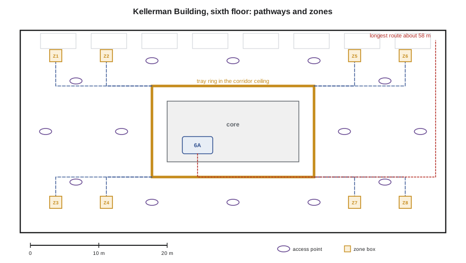
Next is the room. The floor's usable area, about 1,650 m² (17,800 ft²), is more than the 1,000 m² (10,000 ft²) that the TIA-569 planning figure gives to one room, which would suggest a second room. But the area figure is a planning guideline; the distance rule is the hard limit. Because room 6A is in the central core, the longest route on the floor, to the far corner office, measures about 58 m (190 ft) along the pathways before allowances. Every outlet is comfortably inside 90 m, so one room can serve the floor if it can hold the equipment.
# Rack count for room 6A (interconnect: panels and tenant switches in the same racks)
import math
cables = 348
backbone_u, ups_u = 4, 4
rack_u, growth = 45, 0.25
panels = math.ceil(cables * 1.2 / 48)         # 48-port panels, 20 % spare ports
switches = math.ceil(cables / 48)
managers = panels + switches
used = panels * 2 + switches + managers + backbone_u + ups_u
racks = math.ceil(used * (1 + growth) / rack_u)
print(f"panels {panels}, switches {switches}, managers {managers}: {used} U now")
print(f"with {growth:.0%} growth: {used * (1 + growth):.0f} U -> {racks} racks of {rack_u} U")panels 9, switches 8, managers 17: 51 U now with 25% growth: 64 U -> 2 racks of 45 U
Three racks are needed. Room 6A, as built by the landlord, is about 3.2 m by 4.0 m (10.5 ft by 13 ft), which holds three racks in a row with 1 m (3 ft) of working space front and back. Sanjay documents the decision in the design report: one room, justified by route length, with the rack layout attached, and the landlord's approval of the tenant's use of all three rack positions.
Step 4: pathways
The pathway design follows the floor's shape. A 300 mm (12 in) wire-basket tray leaves room 6A and runs in the ceiling of the corridor that rings the core, so that cables can leave in either direction. From the ring, branches of J-hooks run outward to the offices on the perimeter and to the pod zone boxes. Each office's cables drop inside the wall to a low-voltage bracket at the outlet; meeting rooms and the boardroom get short conduit stubs from the boxes to above the ceiling.
Maya checks the tray's busiest section, where it leaves the room: at the start, all 348 cables are in the tray, splitting into two directions of about 174 each within a few metres. With Category 6A at about 7.4 mm (0.29 in) diameter, 174 cables occupy about 7,500 mm² (11.6 in²) of cross-section. A tray 300 mm wide by 100 mm deep (12 in wide by 4 in deep) has 30,000 mm² (48 in²), so the fill is about 25 percent, which is exactly the planned initial fill and leaves room for growth. In the first few metres, where all 348 cables share one section, Sanjay specifies a wider 450 mm (18 in) tray.
The branches use J-hooks at an average of 1.35 m (4.4 ft), never more than 1.5 m (5 ft), with the largest branch, to the north pods, carrying 72 cables on three hooks side by side at each support. PoE bundle size is the last check. The access point and camera cables, the highest PoE loads on the floor, are kept in their own small bundles of no more than 24 cables, separated from the desk cables, as TSB-184-A recommends.
Step 5: backbone and administration
Brightwater's network connects to its head office through a service provider circuit that arrives at the building's entrance facility, and to the building's systems through the landlord's equipment room. Sanjay designs a tenant backbone from the equipment room to room 6A through the building's riser: a 24-strand singlemode cable, enough for two pairs of uplinks to two core switches, the service provider's handoff and generous spares, and a 25-pair copper cable for the alarm communicator, the elevator lobby emergency telephone and analog lines. Both are riser-rated and supported at each floor, and the sleeves are firestopped after the pull.
The identifiers follow the building's standard. The room is 6A; its panels are A to H; horizontal links run from 6A-A01 to 6A-H12; the zone boxes are labelled with their pod and the links they serve; and the backbone cables are ER1/6A-1 for the fibre and ER1/6A-2 for the copper. Maya generates the label files and the outlet schedule from the design list, so every faceplate, panel port and test record will carry the same identifier.
Step 6: takeoff and bill of materials
With the routes drawn, Maya runs the takeoff. She measures the shortest and longest routes for each direction of the ring and checks the average-length method against twenty measured routes; it comes within about 3 percent, so she uses it.
# Brightwater sixth floor: horizontal cable takeoff and main materials
import math
groups = {"north half": (174, 9, 58), "south half": (174, 11, 55)}
allow = 9                       # rack, drop and service loops, m
box = 305
total_len, total_boxes = 0, 0
for name, (n, short, long_) in groups.items():
    avg = (short + long_) / 2 + allow
    per_box = math.floor(box / avg)
    boxes = math.ceil(n / per_box)
    total_len += n * avg
    total_boxes += boxes
    print(f"{name}: {n} cables, average {avg:.1f} m, {per_box} per box, {boxes} boxes")
print(f"cable: {total_len:,.0f} m plus 10 % = {total_len * 1.1:,.0f} m; order {total_boxes} boxes")
print(f"outlet jacks {348}, zone box ports {8 * 24}, panels {math.ceil(348 * 1.2 / 48)}, racks 3")
longest = max(g[2] for g in groups.values()) + allow
print(f"longest cable {longest} m against the {90} m limit: margin {90 - longest} m")north half: 174 cables, average 42.5 m, 7 per box, 25 boxes south half: 174 cables, average 42.0 m, 7 per box, 25 boxes cable: 14,703 m plus 10 % = 16,173 m; order 50 boxes outlet jacks 348, zone box ports 192, panels 9, racks 3 longest cable 67 m against the 90 m limit: margin 23 m
The longest cable, to the far corner office, is well within the limit, and the ceiling over the floor is conditioned office space, so no temperature reduction is needed. The order goes to Colette with the boxes rounded up to full cases, the panels and jacks from the warranted product line, and the zone boxes, tray, hooks and firestop materials from the pathway design.
Step 7: the design review
Before Sanjay stamps the design, Dev reviews it from the installer's side, as he does on every job. His comments are the kind that only field experience produces.
- The zone boxes for the two pods by the windows sit under a bulkhead that hides a large duct. He asks Sanjay to move them 1.5 m (5 ft) toward the core, where the ceiling is open, which keeps their routes over 15 m from the room.
- The landlord's ceiling has seismic bracing wires for the sprinkler mains along the north corridor. The tray must be hung clear of them, and the hooks for the north branch must attach to the slab, not to the bracing.
- The training room's eight outlets include two at a lectern that the tenant has not located. He suggests a floor box with a conduit to the wall, so the lectern can move without new cable.
- The test plan should name the tester's permanent link adapter type and the Category 6A permanent link limit, so the warranty submission is accepted the first time.
Sanjay accepts all four, revises the drawings and issues the design for construction. Maya keeps her copy of the review: it is the best summary of what she has learned, that a design is a set of rules applied to a real building, and that the people who will install it are part of getting it right.
Worked problem
Checking the design against the course's limits
Before the drawings go out, Sanjay asks Maya to check the final design against every rule on his one-page list. What does she confirm?
Show solution
- Horizontal length: the longest cable is about 67 m (220 ft), under 90 m (295 ft); the channel with cords will be well under 100 m.
- Connections: zone box channels have three connections, the panel, the zone box and the outlet, within the four allowed; all others have two.
- Consolidation points: eight, each serving 12 work areas, each at least 15 m from the room.
- Room: one room justified by distance, with three racks and 25 percent growth space; backbone has one level, from the equipment room to 6A.
- Pathways: tray at about 25 percent initial fill, J-hooks at no more than 1.5 m (5 ft), PoE bundles of 24 or fewer cables.
- Administration: identifiers in the building's TIA-606 format, label files generated from the design list, records ready for the building's database.
Answer: Every rule in the course is met, and the one deviation from a planning guideline, a single room for a floor larger than the area figure, is justified by route length and documented.
Common mistakes
MistakeStarting the design with a cable count before checking room locations.
InsteadCheck every outlet's route to its room first; the room decides everything else.
MistakeTreating the area guideline for rooms as a hard limit, or ignoring it.
InsteadUse it to question the design, and justify any deviation with route lengths and rack layouts.
MistakeLeaving device outlets to be added by other trades.
InsteadCount every device that needs a horizontal cable in the design.
MistakePutting zone boxes where the ceiling is blocked.
InsteadLocate them where they can be reached and maintained.
MistakeSkipping the installer's review.
InsteadField review catches problems that drawings hide.
Summary and key terms
- A cabling design starts from the owner's requirements and the building owner's standard.
- The cable count comes from work areas, offices, rooms and every device, with access points on a grid.
- The room's location and the 90 m route rule come first; area guidelines are checked and any deviation justified.
- Racks, pathways and backbone are sized from the count with planned spare capacity.
- Identifiers and labels are generated from the design list, and the takeoff turns the design into an order.
- An installer's review before construction catches the problems of the real building.
- Designer of record
- The person responsible for, and usually stamping, the cabling design.
- Brief
- The owner's or tenant's written statement of requirements.
- Zone box
- A ceiling or floor enclosure housing a consolidation point for a group of work areas.
- Design review
- A check of a design by others, including installers, before it is issued for construction.
- Issued for construction
- The status of drawings approved for use in building the work.
Practice problems
Work each problem on paper first, then reveal the answer to check.
Why does Sanjay accept one room for a floor larger than the area guideline?
Show answer
Every route is well within 90 m from the central room and the room holds the three racks needed; the deviation is documented.
How many cables does each zone box serve, and why that number?
Show answer
24, for 12 work areas of two outlets each; 12 work areas is the maximum per consolidation point.
What fill does the corridor tray have where it carries 174 cables?
Show answer
About 25 percent, the planned initial fill.
Name two items Dev added in the design review.
Show answer
Any two: moving the window-side zone boxes, keeping the tray and hooks clear of seismic bracing, a floor box for the lectern, naming the permanent link adapter and limit in the test plan.
What is the backbone between the equipment room and room 6A?
Show answer
A 24-strand singlemode fibre cable and a 25-pair copper cable, both riser-rated.
Lesson quiz · 5 questions
Score 60% or more to complete this lesson.
Create a free account to save your progress, take quizzes and earn a certificate.