
LVT-120 · Lesson 5 of 12 · 21 min
Horizontal cabling and the channel
Horizontal cabling is the part of a structured cabling system that the building's users actually touch: the cable from the telecommunications room to each outlet, the outlet itself and the cords at each end. It accounts for most of the cable on any job, most of the labour and most of the problems. It is also the subsystem with the tightest limits, because the network equipment at each end, a switch port and a device's network interface, was designed on the assumption that the cable between them would never exceed a defined length or a defined number of connections. This lesson sets out those limits and the reasoning behind them, and shows how Sanjay applies them when the floor plan does not cooperate.
One cable to every outlet
Horizontal cabling follows a star. Each outlet has its own four-pair cable running continuously from a patch panel in the telecommunications room to the outlet, with no splices, no taps and at most one consolidation point along the way. Each cable serves one outlet port. The cable is permanent: it is installed in the building's pathways, terminated at both ends and tested, and nobody moves it when a user moves. What changes are the cords at each end: the patch cords or equipment cords in the telecommunications room and the work area cord at the desk.
That permanence is why horizontal design decisions matter so much. Adding an outlet later costs many times more than installing it during construction, because the ceiling must be opened, a new cable pulled through occupied space and a new port found on a panel that may already be full. Sanjay's rule of thumb, shared by most designers, is that the cheapest outlet is the one installed before the tenant moves in.
The 90 m and 100 m limits
The two lengths that define horizontal cabling are 90 m (295 ft) and 100 m (328 ft). The horizontal cable itself, from the patch panel to the outlet, may be no longer than 90 m. The complete channel, from the switch port to the device, including the horizontal cable and all the patch cords, equipment cords and work area cords, may be no longer than 100 m. The difference, 10 m in total, is the allowance for cords. TIA-568.1 also recommends that the work area cord be no longer than 5 m, leaving the rest for patching and equipment cords in the telecommunications room.
The standard defines two test configurations around these limits. The permanent link is the installed part: the horizontal cable from the patch panel jack to the outlet jack, including those two connections but not the cords. It is what a contractor builds and tests at the end of a job, because the cords that will eventually be used are not yet known. The channel is the complete end-to-end path, with the cords, as the equipment sees it. A channel may contain up to four connections: the patch panel, the outlet, a consolidation point and, in a cross-connect, a second panel. LVT-130 shows how a tester measures each configuration.
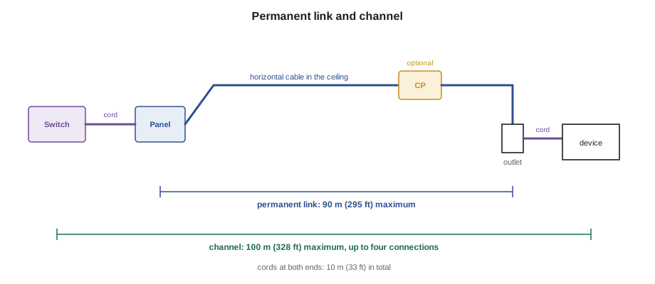
Why 100 m? The limit comes from the signal budget of the network equipment. Every metre of cable and every connection weakens the signal and adds noise. Ethernet transceivers are designed to recover the signal over a channel with a defined maximum insertion loss and minimum crosstalk performance at each frequency, and the 100 m length with four connections is the worst case the standards were written around. A shorter channel simply has margin to spare. Exceeding 100 m does not usually cause a sudden failure; it causes errors, retransmissions and slow or unstable links that are hard to diagnose, which is worse.
Length in practice
The 90 m limit is measured along the cable, and cable routes are always longer than they look. A route from a telecommunications room to an outlet climbs from the panel to the ladder rack, runs along the ceiling pathway around corners and obstructions, drops down a wall to the outlet and includes service loops at both ends, slack left so that the cable can be re-terminated or the outlet relocated slightly. Sanjay's takeoffs add about 3 m (10 ft) at the room end for the rise and the rack, the height of the wall drop at the outlet end, about 3 m (10 ft) of service loop in the ceiling above the outlet and a further allowance of about 10 percent for routing. A straight-line distance of 60 m on the floor plan can easily become 85 m of cable.
Temperature also shortens the allowable length. The insertion loss of copper cable rises with temperature, so a cable in a hot ceiling space has more loss than the same cable at the 20 °C (68 °F) on which its specification is based. TIA-568.2 accounts for this with a length reduction for horizontal cables installed in warm spaces. For unshielded cable, a commonly used figure is about 0.4 percent of length for each degree above 20 °C, up to 40 °C (104 °F), with a larger reduction above that; shielded cable is affected less, about 0.2 percent per degree. Ceilings under roofs and spaces near heating equipment are the usual places where this matters.
Patch cords add one more correction. Cords are made of stranded conductors for flexibility, and many are a thinner gauge than the solid 23 or 24 AWG horizontal cable, such as 26 AWG or even 28 AWG for high-density patching. Stranded and thinner conductors have more loss per metre, so a metre of cord uses more of the channel's loss budget than a metre of horizontal cable. The standards handle this with a derating factor: for the multi-user outlet formula below, 0.2 for 24 AWG cords and 0.5 for 26 AWG cords. In practice it means that the 10 m cord allowance shrinks when thin cords are used, and very long work area cords need a shorter horizontal cable.
# Is this horizontal route inside the limits?
plan_distance = 62       # straight line on the floor plan, m
room_end = 3             # rise from panel to ladder rack and rack routing
wall_drop = 2.5            # ceiling down to the outlet
service_loop = 3         # slack above the outlet
routing = 0.10                 # allowance for corners and detours
ceiling_temp_c = 35   # warm ceiling under the roof, 35 C
LIMIT = 90                  # 90 m permanent link

cable = (plan_distance * (1 + routing)) + room_end + wall_drop + service_loop
derate = 0.004 * max(0, ceiling_temp_c - 20)     # unshielded cable, 20 to 40 C
allowed = LIMIT * (1 - derate)
print(f"estimated cable length: {cable:.1f} m")
print(f"allowed at 35 C: {allowed:.1f} m ({derate:.1%} reduction)")
print("within the limit" if cable <= allowed else "too long: needs another room or a shorter route")estimated cable length: 76.7 m allowed at 35 C: 84.6 m (6.0% reduction) within the limit
This route, under the Hartwell warehouse's office roof, is about 78 m (254 ft) of cable against an allowance reduced to about 85 m (277 ft) by the heat. It passes, but not by much, and an outlet ten metres further away would not.
Outlets in the work area
TIA-568.1 plans the horizontal around work areas, with a long-standing planning figure of one work area for every 10 m² (100 ft²) of usable office space and at least two outlet ports in each. Many owners now ask for more: an office with a desk telephone, a computer, a docking station and a printer may need four, and a conference room needs outlets at the table, at the display wall and in the ceiling for a camera or microphone. In schools and hospitals the counts come from the owner's standard or from the premises standards: TIA-4966 for education and TIA-1179 for healthcare, which sets outlet densities for patient rooms, nursing stations and treatment areas.
A growing share of horizontal cables serve devices rather than people. Wireless access points, cameras, card readers, building automation controllers, digital signage and lighting controllers all connect to the horizontal cabling, usually through an outlet or a plug mounted near the device in the ceiling or on a wall. Wireless access points deserve particular care. TIA's guidance for wireless access point cabling recommends running cable to a grid of locations, roughly every 18 m (60 ft), whether or not every location gets an access point on day one, and many owners now run two Category 6A cables to each location so that the fastest access points can use both ports.
Device cabling is often terminated differently from desk outlets. A camera or access point may be cabled to a surface-mount box or a jack in the ceiling with a short equipment cord to the device, or to a field-terminated plug directly on the end of the horizontal cable. TIA-568.0 calls this direct attachment a modular plug terminated link. It must be tested in its own configuration, and many owners still prefer a jack and a short cord because a damaged cord is easy to replace.
Consolidation points and MUTOAs
Open offices with movable furniture need flexibility at the desk end. A consolidation point puts an interconnection in the horizontal cable, in a ceiling or floor zone box, so that the short cables from the consolidation point to the furniture outlets can be replaced when the layout changes, while the long cable back to the room stays put. TIA-568.1 limits each consolidation point to serving up to 12 work areas and recommends that it be at least 15 m (49 ft) from the telecommunications room, because very short links between closely spaced connections can produce crosstalk and return loss problems.
A multi-user telecommunications outlet assembly, or MUTOA, goes further: the horizontal cables end at a group of outlets mounted on a column or wall in the open area, and long work area cords run from there, through furniture pathways, to each desk. Because those cords are long, the horizontal cable must be shortened to keep the channel within its loss budget. TIA-568.1 gives a formula for the longest work area cord, in which C is the combined length of the work area cord and the cords in the room, H is the horizontal cable length and D is the cord derating factor.
Here W is the longest work area cord and T is the length of the patch and equipment cords in the telecommunications room, with T no more than 7 m (23 ft). The standard caps W at 22 m (72 ft) for 24 AWG cords and 17 m (56 ft) for 26 AWG cords. A MUTOA may also serve no more than 12 work areas, and its cords must be labelled at both ends with the work area they serve.
# Longest work-area cord from a MUTOA (TIA-568.1 formula), lengths in metres
CAP = {24: 22.0, 26: 17.0}          # maximum work-area cord by cord gauge
D = {24: 0.2, 26: 0.5}               # cord derating factor
T = 5.0                              # patch and equipment cords in the room
for gauge in (24, 26):
    for H in (50, 70, 80, 90):
        C = (102 - H) / (1 + D[gauge])
        W = min(C - T, CAP[gauge])
print(f"{gauge} AWG cords, horizontal {H} m: total cords {C:4.1f} m, longest work-area cord {W:4.1f} m")24 AWG cords, horizontal 50 m: total cords 43.3 m, longest work-area cord 22.0 m 24 AWG cords, horizontal 70 m: total cords 26.7 m, longest work-area cord 21.7 m 24 AWG cords, horizontal 80 m: total cords 18.3 m, longest work-area cord 13.3 m 24 AWG cords, horizontal 90 m: total cords 10.0 m, longest work-area cord 5.0 m 26 AWG cords, horizontal 50 m: total cords 34.7 m, longest work-area cord 17.0 m 26 AWG cords, horizontal 70 m: total cords 21.3 m, longest work-area cord 16.3 m 26 AWG cords, horizontal 80 m: total cords 14.7 m, longest work-area cord 9.7 m 26 AWG cords, horizontal 90 m: total cords 8.0 m, longest work-area cord 3.0 m
The output shows the trade-off. With a 50 m horizontal cable, a 24 AWG work area cord may run its full 22 m; with a 90 m cable, it may be only about 5 m, the normal allowance. Thinner 26 AWG cords shorten every case. A MUTOA works well near the telecommunications room and poorly at the far end of a floor.
Worked problem
An open office at the Kellerman Building
A tenant on the Kellerman Building's sixth floor wants a block of 24 open desks served from a column MUTOA in the middle of the block. The horizontal cables from the telecommunications room to the column are about 70 m long, and the furniture dealer's cords to the farthest desks need 16 m (52 ft). The tenant's IT group plans 26 AWG cords and 3 m (10 ft) of patching in the room. Will it work?
Show solution
- The MUTOA can serve at most 12 work areas, so 24 desks need two MUTOAs, one on each of two columns or two assemblies on one column.
- With H = 70 m and D = 0.5 for 26 AWG cords: C = (102 − 70) / 1.5 = 21.3 m.
- W = 21.3 − 3 = 18.3 m, under the 17 m cap for 26 AWG, so the cap governs: 17 m, about 17 m (56 ft).
- The 16 m (52 ft) cords are within that limit, so the design works with two MUTOAs and labelled cords.
Answer: Two MUTOAs, each serving 12 desks, with cords of no more than 17 m, meet the limits; with 90 m horizontal cables they would not.
Common mistakes
MistakePulling a cable as long as the route needs without checking 90 m.
InsteadEstimate the route with rises, drops, service loops and routing allowance before pulling.
MistakeForgetting the heat of a ceiling under a roof.
InsteadReduce the allowable length for warm spaces.
MistakeUsing thin patch cords as if they were horizontal cable.
InsteadApply the cord derating; thin cords use more of the loss budget per metre.
MistakePlacing a consolidation point a few metres from the telecommunications room.
InsteadKeep it at least 15 m (49 ft) away.
MistakeRunning 30 m cords from a MUTOA at the far end of the floor.
InsteadUse the formula; long cords need short horizontal cables.
Summary and key terms
- Each outlet has its own continuous four-pair cable to a patch panel, with at most one consolidation point.
- The horizontal cable may not exceed 90 m (295 ft) and the channel 100 m (328 ft), leaving 10 m for cords.
- The permanent link is the installed cable and its two jacks; the channel includes the cords and up to four connections.
- Real routes are longer than plan distances, and warm ceilings and thin cords reduce the allowable length.
- Plan at least two outlets per work area, plus cabling for wireless access points and other devices on a grid.
- Consolidation points and MUTOAs each serve up to 12 work areas, and MUTOA cord lengths follow the TIA-568.1 formula.
- Horizontal cabling
- Cabling from the horizontal cross-connect in the telecommunications room to the outlets in the work areas.
- Permanent link
- The installed horizontal cable between the patch panel jack and the outlet jack, including those connections.
- Channel
- The complete path from equipment to equipment, including cords, of at most 100 m.
- Service loop
- Slack cable left at a termination so that it can be re-terminated or relocated.
- Derating factor
- A factor that accounts for the higher loss of patch cords compared with horizontal cable.
- MUTOA
- A multi-user telecommunications outlet assembly serving up to 12 work areas through long work area cords.
- Modular plug terminated link
- A horizontal link ending in a plug connected directly to a device, without an outlet jack.
Practice problems
Work each problem on paper first, then reveal the answer to check.
A straight-line distance of 70 m on the plan, with 3 m at the room, a 2.5 m drop and a 3 m service loop, plus 10 percent for routing. Is the route under 90 m?
Show answer
70 × 1.1 + 8.5 = 85.5 m; yes, but with little margin.
What is the allowable horizontal length of unshielded cable in a 30 °C ceiling, using 0.4 percent per degree?
Show answer
90 × (1 − 0.04) = 86.4 m.
Using the MUTOA formula with H = 60 m, D = 0.2 and T = 5 m, what is the longest work area cord?
Show answer
C = 42 / 1.2 = 35 m; W = 30 m, capped at 22 m for 24 AWG cords.
How many work areas may a consolidation point serve?
Show answer
Up to 12.
Lesson quiz · 5 questions
Score 60% or more to complete this lesson.
Create a free account to save your progress, take quizzes and earn a certificate.