
LVT-110 · Lesson 9 of 12 · 19 min
Hand tools, power tools and test equipment
A low-voltage technician's tools fall into four groups: the hand tools for cutting, stripping, terminating and mounting; the power tools for drilling and fastening; the cable installation tools for pulling and fishing cable through buildings; and the test equipment that proves the work. Each group has its own hazards and its own habits of good practice. This lesson introduces all four, with most attention to the multimeter, the instrument Maya will use most often to check power, and to the simple testers she will use before the program's later courses introduce cable certifiers and fibre test sets.
Hand tools
Cable cutters with curved, scissor-like jaws cut copper cable cleanly without crushing it; side cutters are for small wires and cable ties. A cable jacket stripper scores and removes the outer jacket of data cable without nicking the insulation of the pairs inside, and its blade depth must be set for the cable in use. A punch-down tool seats conductors into the insulation displacement contacts of jacks, patch panels and blocks and trims the excess wire; its blade must match the block type, and the cutting side faces the waste end. Screwdrivers, nut drivers, a hex key set, needle-nose pliers, a utility knife with a retractable or self-retracting blade, a tape measure, a level, a stud finder and markers complete the kit.
Most hand tool injuries are cuts, and most cuts come from utility knives used toward the body or the free hand, and from blades left exposed in a pocket or pouch. Cobalt Line requires self-retracting knives and cut-resistant gloves when stripping cable jackets with a knife, and forbids carrying open blades. Screwdrivers are not used as pry bars or chisels, damaged tools are taken out of service, and tools are carried in a pouch or bag rather than in pockets, especially on ladders.
Insulated hand tools, rated and marked for 1,000 V, are required for work on or near exposed energized power conductors, which a low-voltage technician does not do. They are still useful for battery work and inside enclosures where a power section sits beside the low-voltage terminals, but they are not a substitute for staying away from power.
Power tools
The cordless drill and impact driver are the trade's workhorses, used for mounting boxes, brackets, racks and devices and for drilling through studs and joists. Hammer drills and rotary hammers drill concrete and masonry for anchors and sleeves. Hole saws and step bits open device boxes and enclosures. A reciprocating saw or oscillating tool cuts openings in walls and ceilings.
Power tool hazards include entanglement in rotating bits, kickback when a large bit or hole saw binds, eye injuries from chips and dust, hearing damage from rotary hammers, and silica dust from drilling and cutting concrete and masonry. The controls are the familiar ones: safety glasses always; hearing protection for hammer drills and rotary hammers; gloves that are not loose around rotating bits; a firm two-handed grip and the side handle on large drills; a clutch setting on the drill to limit kickback; and dust control for concrete. Ontario regulates silica exposure through its designated substances regulation and occupational exposure limits, and on construction projects contractors control silica dust with water, vacuum dust extraction attached to the tool, and respirators where needed. Cobalt Line's rotary hammers are fitted with dust extraction shrouds connected to HEPA vacuums.
Before drilling into any wall, floor or ceiling, a technician confirms what is inside or behind it. Drilling into a concealed power cable or a pipe is a common and expensive mistake, and drilling into post-tensioned concrete slabs, whose steel tendons are under very high tension, can be dangerous. At Riverside, the slabs are not post-tensioned, but at Juniper Point they are, and every core or anchor in a slab is located by the general contractor's scanning crew and marked before Cobalt Line drills.
Cable installation tools
Pulling cable through a building uses its own family of tools. Fish tapes, steel or fibreglass bands wound on a reel, are pushed through conduit to pull a line or cable back. Glow rods, fibreglass rods that screw together, reach across ceilings and up walls without a pathway. A pull string or mule tape is left in empty conduit for future pulls. Cable carts or spool racks let a technician pull several cables at once from boxes or reels without kinking them. For long or heavy pulls in conduit, a cable lubricant and a pulling grip are used, and the pulling tension is kept within the cable manufacturer's limit, typically about 110 N for a four-pair data cable. Excessive tension stretches the pairs and degrades the cable's performance permanently, which LVT-130 covers.
A tone generator and probe, often called a fox and hound, traces cables. The generator clips onto a cable's conductors at one end and sends an audible tone; the probe, passed over a bundle at the far end, squeals when it reaches the toned cable. It is the quickest way to find an unlabelled cable in a full ceiling or rack. Tone generators should not be connected to cables still connected to active network equipment unless they are designed for it, because the tone can interfere with or be filtered by the equipment.
The multimeter
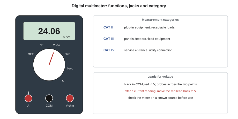
A digital multimeter measures DC and AC voltage, resistance, continuity and, on many models, current, capacitance and frequency. For low-voltage work its most frequent uses are checking power supply outputs, measuring voltage at devices under load, checking fuses and continuity, and measuring the resistance of alarm loops and end-of-line resistors.
- To measure voltage, select the AC or DC voltage function, connect the black lead to the common jack and the red lead to the voltage jack, and place the probes across the two points. The meter has a very high input resistance, so it draws almost no current and does not disturb the circuit.
- To measure resistance or continuity, switch the circuit off, isolate the component or loop, and then measure. The meter applies its own small voltage. Continuity mode beeps below a few tens of ohms and is useful for checking conductors and fuses.
- To measure current with the meter's leads, the circuit must be opened and the meter inserted in series, with the red lead moved to the current jack. Leaving the leads in the current jack and then touching a voltage source shorts the source through the meter's fuse; this is the most common way meters are damaged. A clamp meter, which measures current by the magnetic field around a single conductor, avoids opening the circuit; DC clamp meters use a Hall-effect sensor.
Every meter carries a measurement category rating, such as CAT III 600 V or CAT IV 600 V, which states the transient overvoltages it can withstand safely. Category I and II meters are for electronic and plug-in equipment; Category III is for building distribution such as panels and feeders; Category IV is for the service entrance and utility connections. Although low-voltage technicians mostly measure limited-energy circuits, they work in buildings where a slip can put a probe on a 120 V or higher circuit, so Cobalt Line issues CAT III meters with fused current inputs and leads with shrouded tips, and requires them to be checked on a known source before use.
Two reading problems catch new technicians. The first is the ghost voltage: a high-impedance digital meter connected to a disconnected conductor that runs beside live AC conductors may read tens of volts, induced by capacitive coupling, even though the conductor cannot deliver any current. A meter with a low-impedance mode, often marked LoZ, applies a small load that collapses a ghost reading. The second is a reading on the wrong function or range: measuring 24 V AC on the DC function shows a meaningless value near zero, and some meters do not change ranges quickly enough to catch a brief dip when a lock releases. The minimum and maximum recording feature of a good meter captures such dips.
# Interpreting meter readings on low-voltage circuits (simple rules of thumb)
def interpret(kind, reading, expected=None):
    if kind == "dc_supply":
        dev = (reading - expected) / expected
        return "ok" if abs(dev) <= 0.05 else ("low: check load, fuse, AC input" if dev < 0 else "high: check supply setting")
    if kind == "device_under_load":
        return "ok" if reading >= expected else "too low: measure drop on each conductor and splice"
    if kind == "loop_ohms":
        if reading > 1e6: return "open loop: broken wire or open contact"
        if reading < 50: return "shorted loop: crushed cable or wrong wiring"
        return "within normal range" if abs(reading - expected) / expected <= 0.10 else "abnormal: check terminations"
    if kind == "ghost_check":
        return "likely ghost voltage" if reading < 1.0 else "real voltage present: stop"
for k, r, e in [("dc_supply", 24.2, 24.0), ("dc_supply", 21.9, 24.0), ("device_under_load", 20.1, 21.6),
                ("loop_ohms", 2210, 2200), ("loop_ohms", 1e9, 2200), ("loop_ohms", 3.1, 2200), ("ghost_check", 0.3, None)]:
print(f"{k:<18} reading {r:<10g} -> {interpret(k, r, e)}")dc_supply reading 24.2 -> ok dc_supply reading 21.9 -> low: check load, fuse, AC input device_under_load reading 20.1 -> too low: measure drop on each conductor and splice loop_ohms reading 2210 -> within normal range loop_ohms reading 1e+09 -> open loop: broken wire or open contact loop_ohms reading 3.1 -> shorted loop: crushed cable or wrong wiring ghost_check reading 0.3 -> likely ghost voltage
The ghost check line in the listing models a LoZ reading: a reading that collapses to almost nothing under the meter's load was a ghost, while a reading that holds is a real source. The loop readings show what an alarm or access control input with a 2.2 kΩ end-of-line resistor looks like when healthy, open and shorted.
Cable testers and certifiers
A simple continuity or wiremap tester checks that each conductor of a data cable reaches the right pin at the far end, and reports opens, shorts, reversed pairs and split pairs. It does not show whether the cable will carry high-speed data. A cable certifier does: it measures the electrical performance of the link across its full frequency range against the limits of the standard and stores the results for the owner. Certifiers are expensive precision instruments, and their test leads and adapters wear out and must be replaced on schedule. LVT-130 covers certification testing, and LVT-210 covers fibre test equipment, whose light sources include lasers that must never be viewed directly.
Caring for tools and instruments
Tools that are cleaned, sharpened and stored in order last longer and work better. Punch-down blades and cutters are replaced when they dull, because a dull blade leaves conductors poorly seated or partly cut. Battery packs for cordless tools are stored and charged as their manufacturer specifies, and damaged packs are taken out of service because lithium packs can catch fire. Meters and test sets are kept in their cases, their leads are inspected for cracked insulation before each use, their fuses are replaced only with the rated type, and their calibration is checked on the schedule the company sets. A meter that has been dropped from a ladder is checked on a known source before its readings are trusted.
Worked problem
A card reader that reads 9 V
At Juniper Point, a card reader rated 12 V DC at 150 mA does not light. Maya measures 9.1 V at its terminals with the reader connected. At the supply she measures 12.2 V. The run is short, about 15 m of 22 AWG. What should she check next?
Show solution
- A drop of 3.1 V on a short run at 150 mA implies a loop resistance of about 3.1 / 0.15 = 21 Ω, far more than 15 m of 22 AWG should have, which is under 2 Ω.
- The extra resistance is in a connection. Maya measures with the reader connected: across the positive conductor end to end, 0.02 V; across the negative conductor, 0.03 V; across a splice in the ceiling on the positive side, 3.0 V.
- The splice is a twisted connection with tape instead of a proper connector. She cuts it out and makes a new connection with a rated connector.
- The reader now sees 12.1 V and lights.
Answer: A high-resistance splice dropped 3 V; measuring voltage across each part of the path under load found it.
Common mistakes
MistakeLeaving the meter's leads in the current jack and measuring voltage.
InsteadReturn the red lead to the V jack after any current measurement.
MistakeTrusting a reading on a disconnected conductor that shows 40 V.
InsteadCheck for a ghost voltage with LoZ mode or a loaded tester.
MistakeUsing a dull punch-down blade.
InsteadReplace blades; poor seating causes intermittent faults.
MistakePulling data cable as hard as the puller can.
InsteadStay within the manufacturer's pulling tension.
MistakeDrilling a slab without checking for tendons or conduit.
InsteadHave the slab scanned and marked before drilling.
Summary and key terms
- Hand tool injuries are mostly cuts; use self-retracting knives, cut-resistant gloves and pouches.
- Power tools need eye and hearing protection, firm control and silica dust control for concrete and masonry.
- Fish tapes, glow rods, pull strings and tone tracers move and find cable; respect pulling tension limits.
- Multimeters measure voltage in parallel, resistance on isolated circuits and current in series or with a clamp; choose the right category rating.
- Ghost voltages collapse under load; wiremap testers check continuity, and certifiers check performance.
- Punch-down tool
- A tool that seats conductors into insulation displacement contacts and trims them.
- Fish tape
- A flexible steel or fibreglass band used to pull lines and cables through conduit.
- Tone generator and probe
- A pair of tools that injects a tone on a cable and detects it at the far end.
- Measurement category
- A meter rating, CAT I to CAT IV, for the transient overvoltages of the location where it is used.
- Ghost voltage
- A misleading voltage reading on a disconnected conductor caused by coupling to nearby live conductors.
- LoZ mode
- A low-impedance meter setting that loads the circuit slightly so ghost voltages collapse.
- Cable certifier
- An instrument that measures a cabling link's performance against the limits of a standard.
Practice problems
Work each problem on paper first, then reveal the answer to check.
Which jacks are used to measure DC voltage?
Show answer
COM and V.
A meter reads 38 V on a disconnected cable and 0.2 V in LoZ mode. What was the 38 V?
Show answer
A ghost voltage from capacitive coupling.
What measurement category is suitable for building panels and feeders?
Show answer
CAT III at the system voltage or higher.
Why is a wiremap test not enough for a new data link?
Show answer
It checks continuity and pinning but not high-frequency performance.
Lesson quiz · 5 questions
Score 60% or more to complete this lesson.
Create a free account to save your progress, take quizzes and earn a certificate.