
LVT-110 · Lesson 10 of 12 · 19 min
Reading drawings, specifications and riser diagrams
Before a single cable is pulled, the work exists on paper. Architects and engineers describe the building in drawings and specifications, and Sanjay turns them into the shop drawings, schedules and riser diagrams Cobalt Line's crews build from. A technician who can read those documents works faster, makes fewer mistakes and earns trust; one who cannot spends the day asking where things go. This lesson covers the drawing set, the symbols and conventions used for low-voltage systems, specifications, riser and single-line diagrams, scale and takeoffs, and how changes and record drawings are handled.
The drawing set
A construction drawing set is organized by discipline, each with a letter prefix: A for architectural, S for structural, M for mechanical, E for electrical, and, on larger projects, T for telecommunications or technology, sometimes with separate sheets for security, audio-visual and fire alarm. Each sheet has a title block with the project name, sheet number and title, the designer, the scale, the date and the revision history. The drawing list on the cover sheet shows every sheet and its current revision; checking that the sheet in hand is the current revision is the first habit Dev teaches.
Within a discipline the sheets follow a pattern. Floor plans show each floor from above, with devices, outlets and pathways located on the architectural background. Enlarged plans show crowded areas, such as telecommunications rooms, at a larger scale. Elevations show walls or racks as seen from the front, with mounting heights. Details show how a particular item is installed, such as a firestop through a rated wall or a card reader on a door frame. Schedules list items in tables, such as every door with its hardware and access control devices. Riser and single-line diagrams show how systems connect from floor to floor and room to room without showing their exact physical routes.
Symbols and legends
Devices are shown by symbols, and each drawing set includes a legend that defines them. Symbols vary from designer to designer, so the legend of the current set is the authority, not the symbols remembered from the last job. Common conventions are a triangle for a telecommunications outlet, with a number for the count of jacks; a small square or circle with letters for wireless access points, cameras and readers; and a circle with a letter for speakers. A subscript or tag usually gives the outlet type or mounting height, and a keynote number points to a note on the sheet.
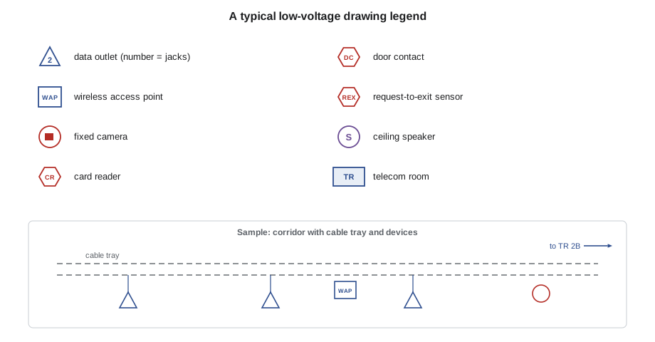
Pathways are shown as lines: cable tray as a pair of lines with its width, conduit as a single line with its size, and J-hooks or other supports by a dashed line or a note. Lines with arrows and tags, called home run arrows, show where a device's cable goes, for example to telecommunications room 2B. Walls with fire ratings are usually shown with a distinctive hatch or line type on the architectural or life safety plans; every place a cable crosses one of those walls needs a firestop.
Scale and dimensions
Drawings are drawn to scale, so that a measured length on the sheet represents a real length. Canadian drawings are usually metric, at ratios such as 1:100 for floor plans, meaning one millimetre on paper represents 100 mm, or 1:50 for enlarged plans. The scale is printed in the title block and often beside each view; a graphic scale bar lets a technician measure from a printed copy that may have been reduced. Dimensions written on the drawing always take precedence over measurement from the drawing, and drawings marked not to scale must not be measured at all.
Plans are increasingly used on tablets as PDF files. A measuring tool in the PDF software, calibrated to the drawing's scale, makes takeoffs fast, but the calibration must be checked against a known dimension on each sheet, because a sheet printed or scanned at a different size changes the scale.
Specifications
The specifications are the written part of the contract documents. They describe the products, the quality of materials and workmanship, and the testing and documentation required. Canadian projects organize specifications by the MasterFormat divisions; telecommunications cabling is in Division 27, Communications, and electronic safety and security, including access control and video, in Division 28. Each section has three parts: general requirements such as submittals and warranties, products with their acceptable manufacturers and performance, and execution, which describes installation, testing and closeout.
When drawings and specifications disagree, the contract usually says which governs, and the technician does not decide: the difference goes to the supervisor, who raises a request for information, RFI, with the design team. Dev's rule for Maya is that she never builds a guess. A question costs a day; a wrong installation hidden in a ceiling can cost a week.
Riser and single-line diagrams
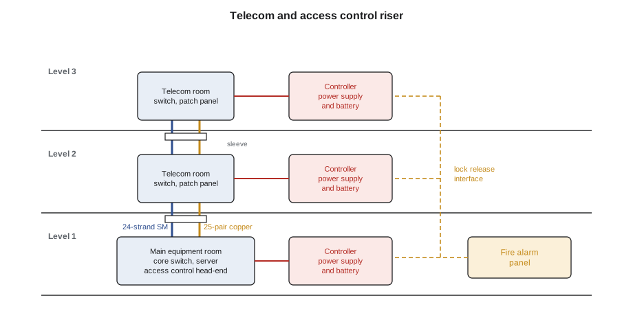
A riser diagram shows how a system is connected vertically through a building, floor by floor, without drawing its physical route. A telecommunications riser shows the main equipment room, the backbone cables to each floor's telecommunications room, their type and count, such as a 24-strand singlemode fibre and a 25-pair copper cable, and the pathway sleeves between floors. An access control riser shows the controllers on each floor, the network connection to the server, the power supplies and their battery backup, and the fire alarm interface. Riser diagrams are the best way to understand a whole system quickly, and Maya keeps one for each system open beside the floor plans.
A single-line or block diagram does the same for a system's logic: for a paging system, the amplifiers, the zones they feed and the inputs from the phone system and the fire alarm; for a camera system, the cameras, the switches that power them and the recorders that store their video. These diagrams are where a technician learns what connects to what, which matters during commissioning and troubleshooting.
Takeoffs and estimating cable
A takeoff is a count and measurement from the drawings: the number of outlets, devices and cables, and the length of each run. Sanjay does the takeoffs for bids, but foremen and technicians do them too, to order material for a floor. The length of a horizontal cable is the distance from the outlet to the telecommunications room along the actual pathway, not a straight line, plus vertical drops at each end, plus slack: service loops at the outlet and in the room, and dressing in the rack. Cobalt Line's rule adds a fixed allowance at each end and then a percentage for waste.
# Cable takeoff for a row of classrooms at Riverside (one-way lengths along the pathway)
SCALE = 0.1                    # real m per drawing mm
measured = {"room 201": 220, "room 202": 300, "room 203": 380, "room 204": 460}   # drawing mm along tray
drops = 6.0        # ceiling to outlet plus tray to room ceiling, m
slack = 6.0       # service loops and dressing at both ends, m
waste = 0.10
outlets = 6           # cables per classroom
total = 0
for room, d in measured.items():
    run = d * SCALE + drops + slack
    total += run * outlets
    print(f"{room}: {run:6.1f} m per cable x {outlets} = {run * outlets:7.1f} m")
order = total * (1 + waste)
box = 305
print(f"total {total:.0f} m, with waste {order:.0f} m = {order / box:.1f} boxes of {box} m")
print("longest run", max(d * SCALE + drops + slack for d in measured.values()), "m; channel limit is 90 m permanent link")room 201: 34.0 m per cable x 6 = 204.0 m room 202: 42.0 m per cable x 6 = 252.0 m room 203: 50.0 m per cable x 6 = 300.0 m room 204: 58.0 m per cable x 6 = 348.0 m total 1104 m, with waste 1214 m = 4.0 boxes of 305 m longest run 58.0 m; channel limit is 90 m permanent link
The takeoff also checks that no run exceeds the length limit of the cabling standard, 90 m for the permanent link of a copper horizontal cable, which LVT-120 covers. A run that would exceed it needs a telecommunications room closer to the outlet, which is a design question for Sanjay, not a field decision.
Changes, marked-up drawings and records
Drawings change during a project. Revisions are issued with clouds around the changed areas and a revision triangle with a number; addenda change the documents before the contract is signed; change orders, RFI responses and site instructions change them after. Obsolete sheets are removed from the site so that nobody builds from them, and the current set, often on tablets, is the only set used.
As work proceeds, the crew marks up a field set to show what was actually installed: the true route of a pathway, a device moved to avoid a duct, an outlet added by a change order, cable labels and test results. At the end of the project those mark-ups become the record drawings, sometimes called as-builts, which go to the owner with the test reports and the warranty. Maya's progress mark-up at Riverside, which she started in her first week, is part of that record, and Dev checks it every Friday.
Worked problem
Finding a card reader's power
Maya is assigned to wire the card reader on door 2.14 at Riverside. Which documents does she use, and what does each tell her?
Show solution
- The door hardware and access control schedule lists door 2.14: a card reader, a door contact, a request-to-exit sensor and a fail-secure electric strike, with the controller and power supply it connects to.
- The second-floor security plan shows the devices at the door, the home run arrow to telecommunications room 2B and the pathway route along the corridor tray.
- The access control riser shows controller C2-1 and power supply PS2-1 in room 2B, with its battery and fire alarm interface.
- A typical door detail shows the mounting heights and the cable entry through the frame; the Division 28 specification gives the cable types and the termination and testing requirements.
Answer: The door schedule, the floor plan, the riser and the typical detail together tell her what to install, where it goes, where it connects and how.
Shop drawings and submittals
Before materials are ordered, the contractor sends submittals to the design team for review: product data sheets for each item specified, and shop drawings that show how the contractor will build what the design shows. Sanjay prepares Cobalt Line's shop drawings for each project, including rack elevations, telecommunications room layouts, door wiring diagrams for each type of door and the labelling scheme. Once the design team reviews and accepts them, they become working documents for the crew alongside the contract drawings.
For Maya, the shop drawings are often the most useful sheets in the set, because they show the details the contract drawings leave out: which port on which patch panel each outlet lands on, which terminal of which controller each door device connects to, and how each cable is labelled. A door wiring diagram, for example, shows every conductor from the reader, the door contact, the request-to-exit sensor and the lock to its terminal, with the cable type and the colours used, so that every door on the job is wired the same way and any technician can service it later.
Shop drawings also protect the contractor. If the design team accepts a shop drawing that shows a detail one way and the owner later asks for it another way, the accepted drawing records what was agreed. Maya keeps the accepted shop drawings with the contract drawings on her tablet and checks that she is using the accepted version, not an earlier draft that was returned with comments.
Common mistakes
MistakeWorking from a sheet without checking its revision.
InsteadCheck the revision against the current drawing list.
MistakeMeasuring from a drawing marked not to scale or reduced in printing.
InsteadUse written dimensions or the graphic scale bar, and calibrate PDF tools on each sheet.
MistakeMeasuring a straight line for a cable takeoff.
InsteadFollow the pathway, add drops, slack and waste.
MistakeResolving a conflict between drawings and specifications on the spot.
InsteadRaise it through the supervisor as an RFI.
MistakeLeaving mark-ups until the end of the job.
InsteadMark up the field set as work is done.
Summary and key terms
- Drawing sets are organized by discipline; title blocks and the drawing list show the current revision.
- Plans, elevations, details, schedules and risers each answer a different question about the work.
- Symbols are defined by the legend of each set; scales differ by sheet and must be checked.
- Specifications in Divisions 27 and 28 describe products, installation and testing; conflicts go to an RFI.
- Takeoffs follow the pathway and add drops, slack and waste; mark-ups become the record drawings.
- Title block
- The area of a sheet that gives the project, sheet number, scale, date and revisions.
- Legend
- The table that defines the symbols used in a drawing set.
- Riser diagram
- A diagram showing how a system connects floor to floor without its physical routes.
- Takeoff
- A count and measurement of materials from the drawings.
- RFI
- A request for information, the formal question to the design team about the documents.
- Record drawings
- Drawings marked up to show the work as actually installed, delivered to the owner.
- MasterFormat
- The standard numbering system for construction specifications, with communications in Division 27 and security in Division 28.
Practice problems
Work each problem on paper first, then reveal the answer to check.
A line measures 48 mm on a 1:100 plan. What is the real length?
Show answer
4.8 m.
Which specification division covers access control and video surveillance?
Show answer
Division 28, Electronic Safety and Security.
What does a cloud with a triangle 3 on a sheet mean?
Show answer
The clouded area was changed in revision 3.
A cable run measures 72 m along the tray plus 6 m of drops and slack. Is it within the permanent link limit?
Show answer
Yes: 78 m is under 90 m.
Lesson quiz · 5 questions
Score 60% or more to complete this lesson.
Create a free account to save your progress, take quizzes and earn a certificate.