
IRW-210 · Lesson 2 of 12 · 23 min
Reading erection drawings
▶ Video coming soon A video version of this lesson is on the way.
On the Wednesday steel night of October 14, Nate spread a set of drawings across the yard table that none of the apprentices had seen before: four sheets marked E1 to E4 for the Linwood Fire Station, a two-storey building Crossbeam would start erecting on October 26, three days after Ashcroft topped out. "Ashcroft you learned by walking it," he said. "This one you are going to learn from paper first, so that when the steel shows up you already know where every piece goes." He gave each apprentice a highlighter and a column line to follow, and for the next two hours they traced the building from the anchor rods to the roof.
This lesson explains the drawings an erection crew works from, how column lines and elevations locate every piece, how piece marks and erection marks tie the steel to the drawing, and how to read the notes and details that tell the crew how each connection is made.
The drawings on a steel job
Several kinds of drawings describe the steel in a building, and an ironworker needs to know which one answers which question.
- Structural design drawings, made by the engineer of record. They show the size of every member, the loads, the connection requirements and the general notes. They are the design, but they do not show every bolt and plate.
- Shop drawings, made by the fabricator's detailer. Each one shows a single piece or a group of identical pieces as the shop will make it, with every hole, plate, weld and dimension. The shop works from them; the field rarely needs them except to settle a question about a piece.
- Erection drawings, also made by the detailer. They show where each piece goes in the building: plans of each level, elevations of the braced bays and frames, anchor rod plans and connection details. They are the field crew's main drawings.
- Anchor rod drawings. A plan of the foundation showing the position, size, projection and pattern of every group of anchor rods, made early so that the concrete crew can set the rods before the steel arrives.
- The erection plan and procedures. For many jobs, a written plan of the sequence, crane positions, bracing and stability measures, prepared by the erector and, where needed, its erection engineer (lessons 9 and 11).
When the drawings disagree, the crew does not choose. The foreperson raises a request for information through the general contractor, and the steel waits.
Column lines and grids
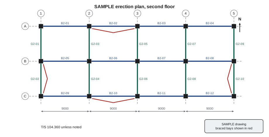
Every building is laid out on a grid of column lines. On most drawings, the lines running one way are lettered and the lines running the other way are numbered, so every column has an address such as B-3, where line B crosses line 3. The grid dimensions show the distance from centre to centre of the lines. Beams are named for the lines they run along and between: a beam on line B from 2 to 3 sits between columns B-2 and B-3.
Grid lines are not always the centrelines of columns. Edge columns are often offset so that their outside face lines up with the building edge, and the drawing shows the offset from the grid. The erection drawings and the anchor rod plan show these offsets, and the column will not fit its rods if the offset is ignored.
Elevations and datums
The height of every piece is given as an elevation measured from a datum, a fixed reference level for the job. Some jobs use a geodetic elevation, the height above sea level; many use a site datum set by the surveyor and called 100.000 or 100 feet so that no elevation is ever negative. The drawings give the top of steel, written T/S or T.O.S., for each beam and the underside of the base plate or the top of the pier for each column.
Top of steel is usually below the finished floor by the depth of the deck and concrete above the beams. Beams that carry different floor finishes, drop to make room for a thicker slab or step at a door may each have their own top of steel, written beside the beam on the plan. A beam set with its top at the finished floor elevation instead of the top of steel will put a hump in the floor that nobody can fix.
Worked problem
Top of steel from finished floor
Linwood's second floor has a finished floor elevation of 104.500 m. The composite slab, deck and concrete together, is 140 mm thick. What is the top of steel for the floor beams?
Show solution
- Top of steel = finished floor − slab thickness.
- T/S = 104.500 − 0.140 = 104.360 m.
Answer: 104.360 m, which is what the plan shows beside each floor beam. Beams under the second-floor washrooms, where the slab is thicker for the floor drains, have their own, lower top of steel marked on the drawing.
Piece marks and erection marks
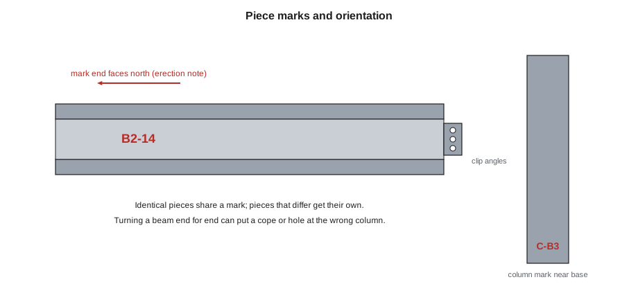
Every piece of steel carries a mark painted or stamped on it by the shop, and the same mark appears on the erection drawing where the piece goes. Fabricators use different systems, but the common pattern is a letter for the type of piece and a number. On the Ashcroft job, Lakeport Steel Fabricators used B for beams, G for girders, C for columns, V for vertical braces and M for miscellaneous pieces, with a digit for the level and a sequence number: B2-14 was beam 14 on level 2.
Identical pieces share a mark, so ten beams marked B2-07 can go in any of the ten places marked B2-07 on the plan. Pieces that look identical but are not, for example a beam with an extra hole for a pipe hanger, get their own mark, and putting one in the wrong place causes trouble later. Some fabricators add an erection mark that is unique to each location, which removes that risk at the cost of more marks.
The mark is painted near one end of the piece, and its position matters. On many jobs the mark end goes toward the north or the east, or toward the lower-numbered grid line, and the erection drawing says so in a note. Columns carry their marks near the base and on the face that goes toward a stated direction. Turning a beam end for end can put a skewed end, a cope or a hole pattern at the wrong column.
Reading the plan
Nate taught the apprentices to read an erection plan in the same order each time.
- Title block and revision. Check the sheet number, the level shown and the latest revision. Working from an old revision is one of the most common causes of field errors.
- Grid and north arrow. Find the column lines and orient the drawing to the building.
- Columns. Find each column mark and its orientation; note any offset from the grid.
- Beams and girders. Follow each line and read the piece marks, the top of steel and any notes about camber, sequence or temporary connections.
- Braced bays and frames. Find the elevations that show the bracing and moment frames; these are the pieces that make the frame stable.
- General notes. Read them all: bolt type and size, connection type, tightening requirements, mark orientation, sequence and any stability notes from the erection engineer.
The general notes on Linwood's E1 said that all bolts were ASTM F3125 Grade A325, 3/4 in diameter, that shear connections were snug-tight unless noted, that brace connections were slip-critical with twist-off bolts, and that the frame was not stable until the braced bays on lines A and C and on lines 1 and 5 were complete. The apprentices circled the last note twice.
Details and symbols
The erection drawings include details of typical connections, drawn as small sections or views with symbols for bolts and welds. A bolt pattern is shown as circles or crosses at each hole, with the number, diameter and type of bolts and any washer requirements. A field weld is shown with the welding symbol and a flag, and a weld that the shop makes has no flag. Camber, a slight upward curve built into a long beam so that it settles flat under load, is shown as a note such as "camber 20 mm" on the beam, and the crowned side goes up.
Detail callouts are bubbles that point from the plan to a detail: a bubble marked 3 over E4 means detail 3 on sheet E4. Section cuts work the same way. Following them every time, rather than assuming a connection is the same as the last one, is how a crew avoids installing the wrong bolts or missing a stiffener.
Worked problem
Counting columns and beams from the grid
A two-storey building has lettered lines A, B and C and numbered lines 1 to 5, with a column at every intersection. Beams run along every line between columns at each of the two floor levels above the ground. How many columns and how many beams on the grid lines are there?
Show solution
- Columns: 3 lettered lines × 5 numbered lines = 15.
- Beams along the lettered lines at one level: 3 lines × 4 spaces = 12.
- Beams along the numbered lines at one level: 5 lines × 2 spaces = 10.
- Grid beams at one level: 12 + 10 = 22; at two levels: 44.
Answer: 15 columns and 44 grid beams, before infill beams between the grid lines, braces and miscellaneous pieces. Linwood has 15 columns, and its piece count, with infill beams, braces and other pieces, is 116.
Revisions and RFIs
Drawings change during a job. Each revision is listed in the title block with a number or letter and a date, and changed areas are often marked with a cloud and a revision triangle. The foreperson keeps the current set and removes superseded sheets from the field; an old sheet left in a gang box is a trap.
A request for information, or RFI, is a written question from the field to the designers, usually sent through the general contractor. The answer may come as a sketch, a revised drawing or a written reply, and it is filed with the drawings. On the Linwood job, Carla's RFI about a rod group that did not match its base plate, covered in lesson 3, was answered the same morning by the engineer of record with a sketch that became part of the drawings.
Drawings in the field
Paper drawings on a steel job have a hard life. They are folded into gang boxes, rained on, written on and left on the deck. Most crews now carry the current set on a tablet as well, with the paper set in the site trailer as the controlled copy. Whichever they use, the rules are the same: one current set, superseded sheets removed or marked void, and field notes, such as a change agreed with the general contractor, written on the controlled copy with the date and the name of the person who agreed it. A tablet makes it easy to zoom in on a detail, but it also makes it easy to open an old file, so Carla's crews check the revision in the title block every morning against the list in the trailer.
Reading the drawings is also a matter of reading the building. Before the first column goes up, the foreperson walks the site with the drawings, looking at what is actually there: the piers and their rod groups, the slab on grade if it is poured, the crane pad, the overhead lines, the neighbouring buildings and the access roads. A drawing shows the building as it should be; the walk shows the site as it is. The differences are the first problems of the job, and finding them early is part of reading the drawings well.
A practice reading
At the end of the October 14 steel night, Nate gave each apprentice a question to answer from the Linwood set. Shay's was: what goes at B-3 on the second floor? The answer took him through four places on the drawings. The plan on sheet E2 showed the column mark at B-3 and four beams framing into it, two girders on line B and two beams on line 3. The piece marks gave him the sizes from the piece list. The top of steel was written beside each beam. A detail bubble on one of the girders pointed to a detail on E4 showing a shear tab connection with three bolts, snug-tight. The general notes on E1 told him the bolts were 3/4 in A325 and that the mark ends faced north. He wrote it all on a card, and Nate checked it against the shop drawings. It was right, and it had taken twenty minutes. "On the job," Nate said, "you will do that in two, but only because you did it slowly first."
Common mistakes
MistakeWorking from an old revision.
InsteadCheck the title block and use only the current set.
MistakeTreating every grid line as the centreline of a column.
InsteadCheck the plan for column offsets from the grid.
MistakeSetting beams to the finished floor elevation.
InsteadSet beams to the top of steel shown, below the finished floor by the slab depth.
MistakeTurning a beam end for end because both ends looked alike.
InsteadFollow the mark orientation note; ends can differ in copes, skews and holes.
MistakeAssuming a connection is the same as the last one.
InsteadFollow every detail callout to its detail.
Summary and key terms
- Design drawings show the design; shop drawings show each piece; erection drawings show where each piece goes.
- Column lines give every column an address; check offsets from the grid at edge columns.
- Elevations come from a datum; beams are set to the top of steel, below the finished floor by the slab depth.
- Piece marks link each piece to the drawing; follow the mark orientation note.
- Read the plan in order: title block, grid, columns, beams, braced bays, general notes.
- Questions go up as RFIs; answers become part of the drawings.
- Erection drawing
- A drawing showing where each piece of steel goes in the building.
- Shop drawing
- A detailed drawing of a piece as the fabricator will make it.
- Column line
- A grid line that locates columns; lettered one way and numbered the other.
- Top of steel
- The elevation of the top of a beam, written T/S.
- Datum
- The reference level from which elevations are measured.
- Piece mark
- The mark on a piece that matches its place on the erection drawing.
- Camber
- An upward curve built into a beam so that it settles flat under load.
- Request for information
- A written question from the field to the designers, called an RFI.
Practice problems
Work each problem on paper first, then reveal the answer to check.
Where is column C-4?
Show answer
Where line C crosses line 4.
Finished floor is 108.000 m and the slab is 165 mm. What is the top of steel?
Show answer
108.000 − 0.165 = 107.835 m.
What does a bubble with 5 over E3 point to?
Show answer
Detail 5 on sheet E3.
Ten beams carry the mark B2-07. Can any of them go in any B2-07 location?
Show answer
Yes, identical pieces share a mark.
Which way is the crowned side of a cambered beam set?
Show answer
Up.
Lesson quiz · 5 questions
Score 60% or more to complete this lesson.
Create a free account to save your progress, take quizzes and earn a certificate.