
HSE-321 · Lesson 5 of 12 · 27 min
Shock and arc flash boundaries
Approach boundaries turn the results of a risk assessment into lines on the floor. The limited approach boundary marks the distance inside which a shock hazard exists for unqualified persons, the restricted approach boundary marks the distance inside which qualified persons need shock protection, and the arc flash boundary marks the distance at which incident energy falls to 1.2 cal/cm² (5.0 J/cm²), the level at which unprotected skin would just begin to suffer a second-degree burn. HSE-224 Lesson 3 explains the shock boundaries and the tables in CSA Z462 and NFPA 70E, and Lesson 4 of this course explains where the arc flash boundary comes from. This lesson is about applying all three boundaries in the crowded, three-dimensional and always-busy spaces of a data centre.
A quick recap of the three boundaries
The shock boundaries depend only on voltage, and whether the conductor is fixed or movable, so they can be read from tables. The arc flash boundary depends on the incident energy calculation, so it comes from the arc flash study and the label. At low-voltage equipment with significant fault current, the arc flash boundary is often much larger than the limited approach boundary. At equipment with very low incident energy, it may be smaller.
| Nominal voltage (phase to phase) | Limited approach, fixed circuit part | Restricted approach |
|---|---|---|
| AC 50 V to 150 V | 1.0 m (3 ft 6 in) | Avoid contact |
| AC 151 V to 750 V | 1.0 m (3 ft 6 in) | 0.3 m (1 ft 0 in) |
| AC 751 V to 15 kV | 1.5 m (5 ft 0 in) | 0.7 m (2 ft 2 in) |
| AC 15.1 kV to 36 kV | 1.8 m (6 ft 0 in) | 0.8 m (2 ft 7 in) |
| DC 100 V to 300 V | 1.0 m (3 ft 6 in) | Avoid contact |
| DC 301 V to 1 kV | 1.0 m (3 ft 6 in) | 0.3 m (1 ft 0 in) |
Look at what this table means for a data centre. Nearly everything in the building, from the 600 V or 480 V switchboards to the 208 V and 415 V RPPs and busway to the roughly 500 V DC battery strings, falls in the band where the limited approach boundary is about a metre and the restricted approach boundary about 30 centimetres. Medium-voltage switchgear has larger boundaries. And the 48 V to 54 V DC busbars in AI racks are below the voltage at which the tables define a shock boundary, although, as Lesson 1 noted, their very high available current creates a serious burn hazard.
Boundaries in electrical rooms
Electrical rooms are designed around the working space that installation codes require in front of equipment, typically about a metre or more of clear space depending on voltage and what is on the opposite side, with enough headroom and at least one entrance, and two entrances for large equipment in many cases. That working space exists so that a qualified person can work at the equipment and move away from it in an emergency. It is not designed to accommodate a large arc flash boundary.
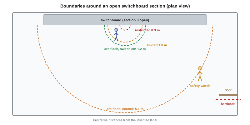
When a switchboard door is opened energized, or covers are removed, the boundaries apply around the exposed parts. In a typical data centre electrical room, the arc flash boundary at main switchgear with normal protection settings may extend several metres, which can cover the entire room and reach into the corridor outside. That has practical consequences that the job plan must address.
- Everyone inside the arc flash boundary must wear arc-rated PPE appropriate to the incident energy at their position, including people who are only watching.
- The safety watch must be positioned outside the arc flash boundary, or wear PPE appropriate to their position, and still be able to see the worker and reach the means of disconnect.
- Other work in the room, such as a mechanical contractor servicing a cooling unit, must stop or move.
- Barricades, signs or an attendant must keep unqualified persons outside the boundary, and the room door may need to be controlled.
- Engaging energy-reducing maintenance switching, as Lesson 4 described, can shrink the boundary enough to make the room workable.
Boundaries in the data hall
Electrical work in the data hall itself creates boundary problems that electrical rooms do not. The hall is full of unqualified persons going about their normal work, the equipment is spread along long aisles and much of it is overhead.
RPPs and PDUs. These stand at the ends of rows or along walls. When an electrician opens an RPP to add a branch circuit breaker, the boundaries extend into the aisle, which may be the only route for IT technicians carrying servers. The job plan should close the aisle with barricades and signs, and post an attendant if the barricade cannot be seen from the work position. Cold aisle containment doors may need to be held or locked so that people do not walk into the boundary from the other side.
Overhead busway. Busway runs above the racks, often 2.5 to 3.5 metres above the floor. Boundaries are three-dimensional, so a worker on a ladder or a mobile elevating work platform near an open tap-off point is inside the boundaries, and so may be a worker installing cable tray on the next ladder. People standing below may also be inside the arc flash boundary, and dropped tools or molten metal from an arc can fall on them. The aisle below should be closed.
Racks and rack power. IT technicians routinely work inside racks that contain rack PDUs and, in AI racks, power shelves and DC busbars. The rack PDU itself, with its receptacles and plugs, is designed so that its live parts are not exposed in normal use, and plugging and unplugging is not electrical work. But removing a power shelf cover or working on the rack busbar is, and the site program must say who may do it and with what precautions.
Busy maintenance windows. In a large maintenance window, electrical, mechanical and IT work may all happen at once. The MOP must lay out which areas are closed at which times, so that a team pulling cable in the next row does not wander into the boundary of an RPP that has been opened energized.
Unqualified persons inside the limited approach boundary
Both standards allow an unqualified person to cross the limited approach boundary only if a qualified person advises them of the hazards and continuously escorts them, and never to cross the restricted approach boundary. In a data centre, this situation arises when an IT technician needs to point out which circuit feeds a rack, when a customer wants to watch a breaker being installed in their cage's RPP or when a commissioning observer needs to see a reading. The escort must actually stay with the person, keep them outside the restricted approach boundary and outside the arc flash boundary unless they are wearing appropriate PPE. Often the better answer is to have the unqualified person watch from outside and let the qualified person do the pointing.
Calculating a barricade distance
The barricade around open equipment should be placed at the larger of the limited approach boundary and the arc flash boundary, so that unqualified persons outside it are protected from both shock and arc flash. The short program below does this for several pieces of equipment at Cedar Ridge, using the summarized shock table and arc flash boundaries taken from the invented labels, and checks whether the barricade would leave a usable walkway in the adjacent aisle.
# Illustrative barricade planning for open equipment (Cedar Ridge, invented labels).
def limited_approach_m(volts, dc=False):
    # summarized from the standards' tables for fixed circuit parts
    if dc:
        return 1.0 if volts >= 100 else 0.0
    if volts < 50:
        return 0.0
    if volts <= 750:
        return 1.0
    if volts <= 15000:
        return 1.5
    return 1.8

equipment = [  # name, volts, dc?, arc flash boundary from label (m), aisle width (m)
    ("Main switchboard A (normal settings)", 600, False, 5.1, 3.0),
    ("Main switchboard A (maintenance switch on)", 600, False, 1.2, 3.0),
    ("RPP A-12 in Hall 1", 208, False, 0.6, 1.8),
    ("Busway tap-off point, Hall 2", 415, False, 1.4, 1.2),
    ("UPS battery string A1", 520, True, 0.9, 1.5),
]
for name, v, dc, afb, aisle in equipment:
    lab = limited_approach_m(v, dc)
    barricade = max(lab, afb)
    left = aisle - barricade
    note = "close the aisle" if left < 0.9 else f"{left:.1f} m walkway left"
print(f"{name:44s} LAB {lab:.1f} m AFB {afb:.1f} m barricade {barricade:.1f} m -> {note}")Main switchboard A (normal settings) LAB 1.0 m AFB 5.1 m barricade 5.1 m -> close the aisle Main switchboard A (maintenance switch on) LAB 1.0 m AFB 1.2 m barricade 1.2 m -> 1.8 m walkway left RPP A-12 in Hall 1 LAB 1.0 m AFB 0.6 m barricade 1.0 m -> close the aisle Busway tap-off point, Hall 2 LAB 1.0 m AFB 1.4 m barricade 1.4 m -> close the aisle UPS battery string A1 LAB 1.0 m AFB 0.9 m barricade 1.0 m -> close the aisle
For most equipment in a data hall, the barricade closes the aisle entirely, which is why electrical work in the white space must be planned with the operations team and, in a colocation facility, coordinated with customers who need access to their cages. At the main switchboard, engaging the maintenance switch shrinks the barricade from more than five metres to just over one, although the room would usually be closed to other work anyway.
DC boundaries and battery systems
UPS battery strings and DC distribution have their own boundaries. Shock boundaries for DC come from separate tables, summarized above, and DC arc flash incident energy is calculated by different methods from AC, which the study should cover. A typical lithium-ion UPS battery string of around 500 V DC falls in the band with a limited approach boundary of about a metre and a restricted approach boundary of about 30 centimetres, the same as low-voltage AC. Because batteries cannot be switched off, the boundaries apply whenever covers or terminal shields are removed, even when the UPS is shut down and isolated. HSE-322 covers battery room work in depth, and Lesson 7 returns to stored energy in the UPS itself.
Emerging higher-voltage DC rack systems, such as the 800 V DC architectures announced for AI racks, fall in the DC band of 301 V to 1 kV. Their boundaries are covered by the existing tables, but the arc flash behaviour of these systems in data hall equipment is still being studied, so sites deploying them must rely on the manufacturer's information and engineering analysis.
Worked problem
Planning boundaries for an RPP breaker installation
A colocation customer at Cedar Ridge has ordered a new 30 A, 208 V circuit to their cage. The electrician will install a breaker in RPP A-12 at the end of row 12 in Hall 1. The site's MOP calls for the RPP to be de-energized at its upstream breaker in the PDU, but the customer's cage and two other customers' racks in row 12 remain in service on their B-side feeds. The aisle beside the RPP is 1.8 m wide. What boundaries and controls are needed?
Show solution
- Once the RPP is isolated, locked out and tested for absence of voltage, the parts inside are no longer energized and the boundaries no longer apply to them. But until then, while covers are removed for testing, the boundaries do apply.
- Determine the boundaries for the testing step: 208 V AC gives a limited approach boundary of 1.0 m and restricted approach of avoid contact; the RPP label gives an arc flash boundary of 0.6 m. The barricade goes at 1.0 m.
- With a 1.8 m aisle, a 1.0 m barricade leaves only 0.8 m, too narrow for a server cart, so the aisle should be closed for the duration of the work and customers told in advance.
- Other customers' racks remain energized from their B-side feeds; the electrician must not open any other equipment, and IT staff working in nearby racks should be told the aisle is closed.
- After the breaker is installed and the RPP is re-energized under the switching order, covers are replaced before the barricade is removed.
Answer: A barricade at 1.0 m during testing and until covers are replaced, which closes the aisle, with customers notified, an escort or attendant to keep unqualified persons out, and no work on other equipment that remains energized.
Common mistakes
MistakeBarricading only at the limited approach boundary when the arc flash boundary is larger.
InsteadPlace barricades at the larger of the limited approach boundary and the arc flash boundary.
MistakeThinking of boundaries only in the horizontal plane.
InsteadTreat boundaries as three-dimensional, including people on ladders, lifts and the floor below overhead busway.
MistakePositioning the safety watch inside the arc flash boundary without PPE.
InsteadPlace the watch outside the boundary, or provide PPE for their position, while keeping sight of the worker and access to the disconnect.
MistakeLetting a customer stand beside an open RPP to watch their circuit installed.
InsteadKeep unqualified persons outside the limited approach boundary unless advised and continuously escorted, and never inside the restricted boundary.
MistakeAssuming boundaries do not apply to batteries because the UPS is shut down.
InsteadRemember batteries cannot be switched off; boundaries apply whenever their live parts are exposed.
Summary and key terms
- The limited and restricted approach boundaries depend on voltage; the arc flash boundary comes from the study and the label.
- Most data centre equipment, AC and DC, falls in the band with a limited approach boundary of about 1.0 m and restricted approach of about 0.3 m.
- At main switchgear the arc flash boundary can cover an entire electrical room unless energy-reducing maintenance switching is engaged.
- In data halls, boundaries usually close aisles, are three-dimensional around overhead busway and must be coordinated with operations and customers.
- Barricades go at the larger of the limited approach and arc flash boundaries.
- Unqualified persons may cross the limited approach boundary only when advised and continuously escorted, and never the restricted approach boundary.
- Limited approach boundary
- The distance from exposed energized parts inside which a shock hazard exists for unqualified persons.
- Restricted approach boundary
- The distance inside which there is an increased likelihood of shock and qualified persons must use shock protection.
- Arc flash boundary
- The distance at which incident energy equals 1.2 cal/cm² (5.0 J/cm²).
- Working space
- The clear space that installation codes require in front of electrical equipment.
- Barricade
- A physical barrier, such as tape, chains or rails, that limits access to an area.
- Attendant
- A person stationed to warn and keep others out of a hazardous area.
- Fixed circuit part
- An energized part that does not move, such as a busbar or terminal.
- Exposed movable conductor
- A conductor that can move, such as an overhead line, for which larger boundaries apply.
Practice problems
Work each problem on paper first, then reveal the answer to check.
What determines the shock boundaries, and what determines the arc flash boundary?
Show answer
Shock boundaries depend on voltage and conductor type; the arc flash boundary comes from the incident energy calculation.
What are the limited and restricted approach boundaries for a 600 V or 480 V switchboard?
Show answer
About 1.0 m (3 ft 6 in) and 0.3 m (1 ft 0 in).
Why can the arc flash boundary at main switchgear cover a whole electrical room?
Show answer
High fault current and delayed clearing give high incident energy, so the 1.2 cal/cm² point is several metres away.
Where should a barricade be placed around open equipment?
Show answer
At the larger of the limited approach boundary and the arc flash boundary.
Give two reasons electrical work on overhead busway needs special boundary planning.
Show answer
Boundaries are three-dimensional, so people on nearby ladders and below are inside them, and dropped objects or molten metal can fall on people below.
When may an unqualified person cross the limited approach boundary?
Show answer
Only when advised of the hazards and continuously escorted by a qualified person.
Do shock boundaries apply to a UPS battery string when the UPS is shut down?
Show answer
Yes, whenever live parts are exposed, because the batteries remain energized.
Which DC band does an 800 V DC rack system fall in?
Show answer
301 V to 1 kV, with a limited approach boundary of about 1.0 m and restricted approach of about 0.3 m.
Where should the safety watch stand during energized work?
Show answer
Outside the arc flash boundary, or with appropriate PPE, with sight of the worker and access to the disconnect.
What effect does energy-reducing maintenance switching have on boundaries?
Show answer
It shrinks the arc flash boundary by shortening clearing time; it does not change shock boundaries.
Lesson quiz · 5 questions
Score 60% or more to complete this lesson.
Create a free account to save your progress, take quizzes and earn a certificate.