
FAT-220 · Lesson 5 of 12 · 20 min
Notification appliance installation rules
With the north wing's ceilings closed on the second floor, Sasha and Gerry hang the first run of horn-strobes in the corridor. Halfway down, Sasha notices that the strobe she has just mounted sits on the far side of a door frame, where anyone in the corridor beyond would see it only at an angle, and that a new exit sign has been hung directly beneath it. 'The drawing put it there before the door was framed,' Gerry says. 'The drawing isn't the building.' They move it a short distance, within the spacing the design allows, and mark the change on the as-built set. FAT-120 covered how audible and visual appliances are selected and spaced. This lesson covers how they are installed: mounting, synchronization, the signals they sound, how audibility is checked after installation, and the special rules for hospitals and sleeping areas.
General rules for notification appliances
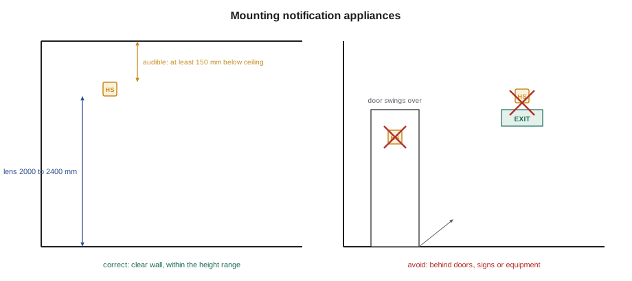
Like initiating devices, notification appliances must be listed for their purpose, compatible with the circuit or power supply that drives them, installed to their listing and the maker's instructions, and mounted securely on listed boxes or to the structure. Strobes and horn-strobes are set to the candela and sound output the design specifies; many modern appliances have selectable settings, and a wrong switch position is a common installation error. Appliances are not mounted where they will be blocked, by doors that swing open over them, by signs, shelves or equipment, or by architectural features the drawing didn't show.
CAN/ULC-S524 sets the mounting heights. Audible signal devices on walls are mounted at least 2,300 mm above the floor and at least 150 mm below the ceiling, unless their listing requires otherwise. Wall-mounted visual signal devices are mounted with the lens between 2,000 mm and 2,400 mm above the floor. Ceiling-mounted appliances follow their listing. Combination appliances follow the stricter requirement or their listing for the combination.
Synchronization
Flashing lights at certain rates can trigger seizures in people with photosensitive epilepsy, and several unsynchronized strobes in view at once multiply the effective flash rate. CAN/ULC-S524 requires visual signal devices within a common field of view to flash in synchronization. In practice, all strobes in a building are synchronized, using listed synchronization modules or panel circuits that send a sync pulse, and the appliances must be listed for the synchronization protocol used. Strobes on different circuits or different power supplies must be synchronized with each other too, which the designer arranges by choosing compatible equipment and connecting the sync signal between supplies.
Synchronization is easy to lose in alterations. When Willowbank School added its summer wing, the new strobes came from a different maker than the existing ones, and the new wing's strobes visible down the main corridor flashed out of step with the old ones. The fix was to replace the old corridor strobes with the new maker's appliances, so that the whole corridor ran on one protocol. Mixing makers on a circuit, or in a common field of view, is generally not possible unless both are listed for the same protocol.
Audible signals are synchronized too. The temporal pattern used for evacuation must be heard as one pattern, not several overlapping patterns, and horns on different circuits that sound out of step make the pattern unrecognizable. Synchronization modules and panel circuits handle the audible sync as well, and some systems allow the horns to be silenced while the strobes keep flashing, which needs the separate horn and strobe control that the appliance and circuit must support.
The evacuation signal
The evacuation signal in Canada is the temporal-three pattern: three half-second tones with half-second gaps, then a pause, repeated, as described by the international standard for evacuation signals. The National Building Code and CAN/ULC-S524 require it for the alarm signal. In a two-stage system, the alert signal has a different, distinct pattern that tells staff an alarm has been initiated without telling occupants to leave. The alert and alarm signals must be easily distinguished, and staff must be trained to recognize both.
| Pattern part | Duration |
|---|---|
| Tone | 0.5 s on |
| Gap | 0.5 s off |
| Tone | 0.5 s on |
| Gap | 0.5 s off |
| Tone | 0.5 s on |
| Pause | 1.5 s off |
| Cycle | 4.0 s, then repeat |
Checking audibility after installation
The design calculates how loud each area will be, but the installer has to show that it actually is. After the appliances are installed and the building is near its final condition, with doors hung and furniture in place where possible, the sound level is measured with a sound level meter, using the A-weighting that approximates human hearing, at the locations and heights the standard specifies, typically about 1.5 metres above the floor. The measurements are compared with the ambient sound level of the space and with the minimum and maximum levels the standard sets.
CAN/ULC-S524 and the National Building Code require the alarm signal to be at least 10 dBA above the ambient sound level, and not less than 65 dBA, in each area, with higher levels in sleeping rooms, measured with the room's door closed. The maximum level near any appliance is limited to protect hearing. Where the ambient level is high, such as in a mechanical room, visual signals may be added to supplement the audible signal.
# Audibility check from measurements (dBA); requirements as given in the lesson
need_above_ambient = 10
minimum = 65
maximum = 110
rooms = [("corridor 2N", 48, 81), ("nurse station 2", 55, 66), ("mechanical 2", 78, 85), ("patient room 2-114", 38, 62)]
for name, ambient, measured in rooms:
    required = max(ambient + need_above_ambient, minimum)
    ok = required <= measured <= maximum
print(f"{name:20s} ambient {ambient:3d} required {required:3d} measured {measured:3d} {'OK' if ok else 'FAIL'}")corridor 2N ambient 48 required 65 measured 81 OK nurse station 2 ambient 55 required 65 measured 66 OK mechanical 2 ambient 78 required 88 measured 85 FAIL patient room 2-114 ambient 38 required 65 measured 62 FAIL
The check flags two places. The mechanical room needs visual signals to supplement the audible signal, or a louder appliance, because its ambient level is high. The patient room falls short of the general minimum, but whether that matters depends on the hospital's notification strategy, covered in the next section and in Lesson 9: in a hospital, patient rooms may be intentionally excluded from the general audible signal, with staff alerted instead.
Hospitals and other places where people aren't expected to leave on their own
In hospitals and similar care facilities, patients can't be expected to evacuate themselves when the alarm sounds, and a loud alarm throughout patient areas could do harm. The National Building Code allows two-stage systems and other arrangements in these buildings, and CAN/ULC-S524 covers how signals are provided: the alert signal goes to staff locations, such as nurse stations, so that staff begin their fire procedures, and audible signals in patient rooms may be omitted or reduced where the code permits, with visual signals and staff alerting taking their place. Eastview's north wing uses a two-stage system, as the rest of the hospital does, with alert signals at nurse stations and the general alarm sounding throughout only if the alert is not acknowledged and cleared within the set time or if a second-stage device is operated.
Hospital notification is designed with the hospital's own fire plan, because the signals must fit the staff's procedures. Ravi's design was reviewed by the hospital's safety officer before it went to the authority, and the crew installs exactly what the design shows: putting a full horn-strobe in a patient room where the design calls for a visual-only appliance would break the hospital's plan.
Sleeping areas and the low-frequency signal
In buildings with sleeping rooms, such as Riverlight Tower's apartments, the alarm must wake people. The required sound level in sleeping rooms is measured with the door closed, and recent editions of the standards require a low-frequency signal, around 520 Hz, which is more effective at waking people, especially people with hearing loss and people who are deeply asleep. Visual signals in sleeping rooms, where required, are of high intensity, because a sleeping person must be woken by the light rather than simply notice it.
Wiring and power for notification circuits
Notification appliances are wired in and out on their terminals so that the circuit stays supervised, with the end-of-line device at the last appliance or as the circuit's listing requires, as FAT-130 covered. T-taps are not used on supervised notification circuits. Each circuit's actual load is checked against the design's voltage-drop calculation: if the installer adds appliances or changes candela settings in the field, the calculation must be redone, because the last appliance may no longer get enough voltage.
The installer records each appliance's candela setting, sound setting and circuit on the as-built drawings, so that the verification technician can check them and the next technician knows what is installed. A strobe set to 15 candela where the drawing shows 75 is a deficiency even if it looks bright.
Worked problem
The second-floor corridor
On the north wing's second floor, Sasha's pre-test finds three things: one strobe has been mounted with its lens below the minimum height because a duct was in the way, two appliances are set to a lower candela than the drawing shows, and the strobes at the far end flash out of step with those near the nurse station. What should she do?
Show solution
- Relocate the low strobe to a point along the wall that meets the height range, within the spacing allowed, or ask the designer for a ceiling-mounted appliance; record the change.
- Set the two appliances to the candela shown on the drawing, and check that the circuit's load still matches the voltage-drop calculation.
- Investigate the synchronization: check whether the far-end strobes are on a different circuit or power supply, whether the sync connection between supplies is made, and whether all the appliances are listed for the same protocol.
- Repeat the test and record the results before the formal verification.
Answer: Each fault is corrected at its cause, and the records are updated, so that the formal test finds a working system.
Visual signals and the people who need them
Visual signals exist mainly for people who are deaf or hard of hearing, and for places where the audible signal can't be heard. Accessibility law, as well as the fire codes, drives where they are required: corridors, washrooms, meeting rooms, classrooms and other spaces used by the public or by employees, with specific rules for sleeping rooms intended for people with hearing loss. The design locates visual signals where they are required, and the installer's job is to mount them so they can actually be seen.
Line of sight is the practical test. A strobe on the far side of a column, behind a hanging sign or above a high shelf may meet its spacing on paper but be invisible from part of the room. Sasha's habit, after a room is finished, is to stand in its corners and doorways and check that a strobe is visible, directly or by its reflected light, from each place. Where it isn't, she reports it rather than leaving it for the verification to find.
Visual signals also have to be installed so they don't confuse. Strobes for fire alarm are clear or white in most applications, and other colours are reserved for other signals, such as amber for mass notification in some buildings. An appliance with the wrong lens colour, or labelled with the wrong word, such as 'ALERT' where the design calls for 'FIRE', is a deficiency even though it flashes correctly.
Protecting notification appliances
Like initiating devices, notification appliances need protection where they could be damaged. Gymnasiums, loading docks and parking structures get listed guards, which must be listed for use with the specific appliance so that they don't reduce its light or sound output below its rating. Appliances in wet or outdoor locations must be listed for those conditions, often with a weatherproof back box. Appliances in the psychiatric unit at Eastview are tamper-resistant types fixed with security screws, as the design specifies.
Speakers for voice systems are covered in FAT-310, but the same mounting and protection rules apply. A speaker in a high-noise area may need a horn-type speaker rather than a ceiling speaker, and its tap setting is part of the voice system's design, recorded like a strobe's candela setting.
Common mistakes
MistakeMounting a strobe where a door or sign blocks it.
InsteadCheck the field location and move it within the allowed spacing.
MistakeLeaving appliance candela or tone switches at the factory setting.
InsteadSet each appliance to the design value and record it.
MistakeMixing appliance makers in one field of view.
InsteadUse appliances listed for the same synchronization protocol.
MistakeMeasuring audibility with doors open and the space empty.
InsteadMeasure in the conditions the standard specifies, with sleeping room doors closed.
MistakeInstalling full public signals in hospital patient rooms against the design.
InsteadFollow the design, which matches the hospital's fire plan.
Summary and key terms
- Notification appliances are listed, compatible and set to the design values.
- Mounting heights and clear locations let them be seen and heard.
- Strobes in a common field of view must be synchronized, and so must audible patterns.
- The temporal-three pattern is the evacuation signal.
- Audibility is measured after installation against the ambient level and limits.
- Hospitals use two-stage alert signals to staff, with notification arranged around the fire plan.
- Sleeping areas need a low-frequency signal and high-intensity strobes where required.
- Synchronization
- Making strobes flash, and horns sound, in step.
- Temporal-three pattern
- Three half-second tones with gaps, then a pause, repeated.
- A-weighting
- A filter on a sound level meter that approximates human hearing.
- Ambient sound level
- The normal background sound level of a space.
- Candela setting
- The selectable light output of a strobe.
- Low-frequency signal
- An audible signal around 520 Hz, used to wake sleepers.
Practice problems
Work each problem on paper first, then reveal the answer to check.
Why must strobes in a common field of view be synchronized?
Show answer
Unsynchronized strobes multiply the flash rate and can trigger seizures.
What is the cycle time of the temporal-three pattern?
Show answer
4 seconds: three 0.5 s tones with 0.5 s gaps and a 1.5 s pause.
Where is audibility measured relative to the floor?
Show answer
About 1.5 m above the floor.
An installer adds two strobes to a circuit in the field. What must be redone?
Show answer
The circuit's voltage-drop calculation.
Why do sleeping areas need a low-frequency signal?
Show answer
It is more effective at waking people.
Lesson quiz · 5 questions
Score 60% or more to complete this lesson.
Create a free account to save your progress, take quizzes and earn a certificate.