
FAT-220 · Lesson 10 of 12 · 21 min
Plans, specifications and shop drawings
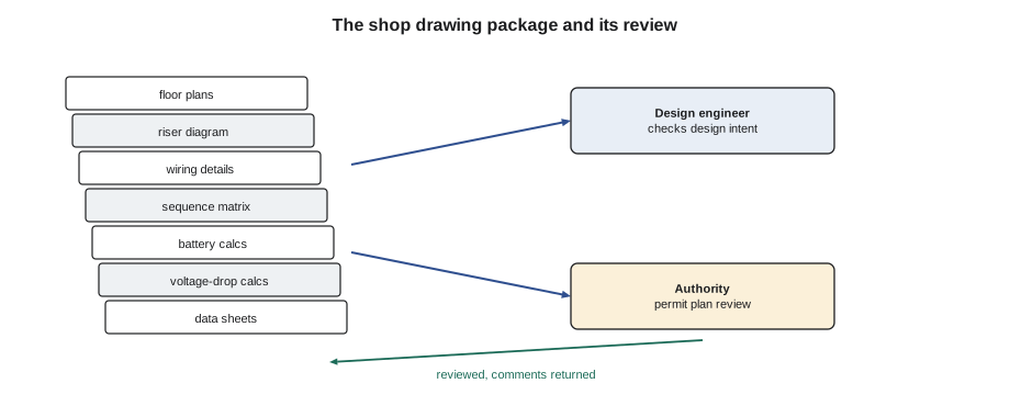
Before Bramwell won the north wing contract, the hospital's consulting engineer issued a set of design drawings and a specification for the fire alarm. Before Bramwell could install anything, Ravi had to turn those into shop drawings: detailed drawings showing exactly which devices Bramwell would install, where, with what addresses, on which circuits, powered from which supplies, and with the calculations to prove it all works. The shop drawings went to the engineer for review and to the authority for the permit. Sasha spends a morning with Ravi going through the package. 'The installer builds from the shop drawings,' he says, 'so if something's wrong on them, it'll be wrong in the ceiling.' This lesson covers the documents that come before installation: the design drawings and specification, the shop drawings and calculations, the submittals and reviews, and how the crew uses them in the field.
Who produces what
On a typical project, three groups produce documents. The owner's design team, usually a consulting electrical or fire protection engineer, prepares the design drawings and the specification, which define what the system must do and the standard of quality. The fire alarm contractor's designer, here Ravi, prepares the shop drawings, which show the specific equipment and layout that will meet the design. And the manufacturers provide the data sheets, installation instructions and compatibility documents for the equipment. The authority reviews the documents needed for a permit, and the design engineer reviews the shop drawings to confirm they meet the design intent.
Designers of fire alarm systems in Canada are usually professional engineers, or work under one, because the provincial engineering acts and the building code's design requirements generally need a professional to take responsibility for the design of building systems. Saskatchewan's requirements for professional design apply to buildings of the north wing's size and type. The fire alarm contractor's designer works within the engineer's design, and many contractors' designers hold technologist or fire alarm qualifications.
The design drawings and specification
The design drawings show the system's intent: the device types and approximate locations, the zoning, the notification arrangement, the interfaces to other systems, and the riser concept. The specification sets the performance and quality requirements: the system type, the acceptable manufacturers, the cable types, the testing requirements, the documentation the contractor must provide, and the training and warranty. Where the specification is stricter than the code or standard, it governs the project, because it is part of the contract.
Design drawings are often less detailed than shop drawings, and they sometimes contain errors or conflicts with the architectural or mechanical drawings. Part of the shop drawing designer's job is to resolve those, by asking questions through the formal channel the contract sets, usually a request for information, so that the answer is recorded. On the north wing, Ravi's requests included where the smoke barrier on the third floor would actually be, which elevator lobby was on the designated recall floor, and whether the psychiatric unit's rooms needed tamper-resistant detectors.
What shop drawings contain
CAN/ULC-S524 and the authority set what the installation documents must show, and the specification usually adds more. Shop drawings for a system like the north wing's typically include: floor plans with every device located and identified by type and address, circuit and zone boundaries, and conduit or cable routes for risers and Class A returns; a riser diagram showing the control units, transponders, power supplies, annunciators and their interconnections; wiring diagrams for typical devices and for every interface to another system; the equipment list with data sheets; the battery and voltage-drop calculations; the sequence of operation or input and output matrix; and the zone list or device descriptions for the annunciator.
The floor plans are drawn to scale, with a legend of symbols, and use the building's final room numbers. The riser diagram is the one drawing that shows the whole system at once, and it is what the verification technician and future service technicians use to understand the system's architecture. The calculations must match the drawings exactly: if the floor plan shows twelve horn-strobes on a circuit and the voltage-drop calculation shows eleven, one of them is wrong.
Calculations
The battery calculation and the voltage-drop calculations, which FAT-130 covered in detail, are the main calculations in a shop drawing package. Others may include the speaker tap and amplifier loading for a voice system, the signalling line circuit's loading and length against the maker's limits, and, in a performance-based design, the detector response analysis. Each calculation states its inputs and their sources, such as the maker's data sheet currents at the design voltage, so that a reviewer can check it.
# Cross-check: device counts on the plans match the counts in each calculation
plans = {"NAC-N2-1": 12, "NAC-N2-2": 10, "NAC-N3-1": 13, "SLC-N1": 148}
vdrop = {"NAC-N2-1": 12, "NAC-N2-2": 10, "NAC-N3-1": 12}
slc_load = {"SLC-N1": 148}
for c, n in plans.items():
    calc = vdrop.get(c, slc_load.get(c))
    status = "matches" if calc == n else f"MISMATCH: plans {n}, calculation {calc}"
    print(f"{c:9s} {status}")
print("Recalculate any circuit that does not match before submitting.")NAC-N2-1 matches NAC-N2-2 matches NAC-N3-1 MISMATCH: plans 13, calculation 12 SLC-N1 matches Recalculate any circuit that does not match before submitting.
Ravi's check finds that NAC-N3-1 has one more appliance on the plan than in its voltage-drop calculation, because an appliance was added in a late revision. The calculation is rerun with thirteen appliances; the last appliance still gets enough voltage, but only just, and the result is noted for the field: no more appliances on that circuit without a new calculation.
Submittals and review
The shop drawing package is submitted to the design engineer, who reviews it against the design and the specification and returns it with a status, such as 'reviewed, no exceptions', 'reviewed as noted' or 'revise and resubmit'. The engineer's review doesn't relieve the contractor of responsibility for meeting the code; it confirms general conformance with the design. The package, or the parts the authority needs, is also submitted for the permit, and the authority's plan reviewer may issue comments that must be addressed before the permit is issued.
In Saskatoon, the fire alarm work is part of the building permit for the north wing, and the city's plan review covers the fire alarm documents. The fire department may also review the annunciator location and the fire department connection details. Work can start once the permit is issued, but any part of the work shown on drawings marked 'revise and resubmit' waits until the revised drawings are reviewed.
Reviewers' comments are answered in writing and the drawings revised. Each revision is numbered and dated, and the changes are clouded or otherwise marked so that everyone can see what changed. The crew in the field must always work from the current revision; a common cause of installation errors is a crew working from a printed set two revisions out of date.
# Submittal and document tracker: what is still outstanding before installation can start
docs = [("floor plans L1-L6", "rev 3", "reviewed as noted"),
        ("riser diagram", "rev 2", "reviewed, no exceptions"),
        ("sequence of operation", "rev 2", "revise and resubmit"),
        ("battery calculations", "rev 3", "reviewed, no exceptions"),
        ("voltage-drop calculations", "rev 3", "reviewed as noted"),
        ("data sheets and compatibility", "rev 1", "reviewed, no exceptions"),
        ("building permit", "-", "issued")]
for name, rev, status in docs:
    ok = status in ("reviewed, no exceptions", "reviewed as noted", "issued")
print(f"{name:30s} {rev:6s} {status:26s} {'ready' if ok else 'HOLD: resubmit'}")floor plans L1-L6 rev 3 reviewed as noted ready riser diagram rev 2 reviewed, no exceptions ready sequence of operation rev 2 revise and resubmit HOLD: resubmit battery calculations rev 3 reviewed, no exceptions ready voltage-drop calculations rev 3 reviewed as noted ready data sheets and compatibility rev 1 reviewed, no exceptions ready building permit - issued ready
Using the drawings in the field
The crew installs from the current reviewed shop drawings, and from the maker's installation instructions for each device. Each installer carries the drawings for the area they are working in and marks on them, in a consistent colour, every difference between the drawing and what was actually installed: a device moved a short distance to avoid a beam, a cable route changed, a junction box added. These marked-up drawings, often called the redlines, are the raw material for the record drawings Lesson 11 covers.
Differences that change the design, such as a detector that can't be placed within the spacing rules, a circuit that needs more appliances, or a device that can't go where the drawing shows it, aren't decided in the field. They are reported to the designer, who issues a revised drawing or a field instruction, so that the change is reviewed and recorded. Sasha learns to tell the difference: a detector moved half a metre along a corridor within the spacing rules is a redline; a detector that has to be deleted because the room was redesigned is a design change.
Coordination drawings are another tool on busy projects. The trades overlay their routes and equipment on one set of ceiling plans to find clashes before installation, such as a detector location that falls on a light fixture or a cable route that crosses a duct. Resolving clashes on paper is much cheaper than in the ceiling.
When the design and the building disagree
Buildings change during construction. Walls move, rooms are combined, ceilings are lowered, mechanical equipment is substituted. Each change may affect the fire alarm: a lowered ceiling changes spacing, a combined room may need fewer devices or more, a substituted air handler may need a different duct detector housing. The fire alarm designer reviews architectural and mechanical changes as they are issued and revises the shop drawings, and the crew needs to hear about them before it installs to the old layout.
The north wing had one such change in the second month: the hospital decided to convert two patient rooms on the fourth floor into a medication room and a staff lounge. The medication room needed a smoke detector and a strobe; the staff lounge, with a kitchenette, needed a heat detector instead of a smoke detector because of cooking. Ravi revised the drawings, reran the voltage-drop calculation for the affected circuit, and issued revision 4 before the ceiling in that area was closed.
Worked problem
The out-of-date drawing
A crew installing the north wing's fourth floor finds that the drawing they are using shows a smoke detector in a room the architect has since turned into a staff lounge with a kitchenette. The drawing is revision 3; revision 4 was issued last week. What should happen?
Show solution
- Stop work in that area and get the current revision from the office; check the revision block on every sheet in use.
- Revision 4 shows a heat detector in the lounge instead of a smoke detector. Install to revision 4.
- Check whether anything else on the floor changed between revisions, using the clouded changes on revision 4.
- Collect and mark the revision 3 prints as superseded so they aren't used again.
- Record the event; if anything was installed to revision 3, correct it and note it on the redlines.
Answer: The crew installs to the current reviewed drawing, and the office's document control makes sure only current drawings are on site.
Product substitutions
Specifications often name acceptable manufacturers or require specific products, and a contractor who wants to use something else must ask for approval of a substitution before installing it. The request shows that the substitute meets the specification and the code, with its data sheets, listings and compatibility documents. For fire alarm equipment, compatibility is the usual sticking point: a substitute detector or appliance must be listed as compatible with the control unit and the synchronization protocol, and a substitute control unit must be compatible with every existing device it connects to.
On the north wing, the specification required the new node to match the hospital's existing network, so substitution of the control equipment was not an option. Ravi did request one substitution, for the air-sampling detectors in the operating suite, and it was approved after the engineer confirmed the substitute's listing and sensitivity range. The approval letter went into the project file, because a future reviewer seeing a different make from the specification would otherwise wonder why.
Shop drawings for alterations
When an existing system is altered, the shop drawings show both the existing equipment that remains and the new work, clearly distinguished, usually by line weight or a legend. They also show any existing equipment to be removed. The calculations are redone for the circuits and supplies affected, using the existing devices' actual loads as well as the new ones. And the sequence of operation is updated to include the new inputs and outputs. On the north wing, the shop drawings include the hospital's existing main control unit and network, showing where the new node connects and how the existing annunciators are reprogrammed to show the wing's zones.
Common mistakes
MistakeInstalling from an outdated revision.
InsteadCheck the revision block and use only current reviewed drawings.
MistakeMaking design changes in the field.
InsteadReport changes that affect the design; the designer revises and records them.
MistakeLetting the calculations drift from the drawings.
InsteadCross-check device counts on the plans against every calculation.
MistakeAssuming the engineer's review transfers code responsibility.
InsteadThe contractor remains responsible for meeting the code.
MistakeNot marking field differences as work proceeds.
InsteadKeep redlines current; they become the record drawings.
Summary and key terms
- The design team sets the intent; the contractor's shop drawings show the specific installation.
- Shop drawings include plans, a riser diagram, wiring details, the sequence of operation, calculations and data sheets.
- Calculations must match the drawings exactly.
- The design engineer and the authority review the submittals; work follows the current reviewed revision.
- Field differences are recorded on redlines; design changes go back to the designer.
- Building changes during construction must flow into revised fire alarm drawings.
- Specification
- The contract document that sets the system’s performance and quality requirements.
- Shop drawings
- The contractor’s detailed drawings of the specific equipment and layout.
- Riser diagram
- A drawing showing the system’s equipment and interconnections on all floors.
- Submittal
- A document package sent for review.
- Request for information
- A formal question to the design team, with a recorded answer.
- Redlines
- Field-marked drawings showing differences between the design and the installation.
Practice problems
Work each problem on paper first, then reveal the answer to check.
Who prepares the shop drawings on a typical project?
Show answer
The fire alarm contractor's designer.
What does 'revise and resubmit' mean for the work shown?
Show answer
It waits until revised drawings are reviewed.
A detector must move within the spacing rules to avoid a beam. What is it?
Show answer
A redline, recorded on the field drawings.
What must match the number of appliances on a circuit's floor plan?
Show answer
The circuit's voltage-drop calculation.
Why are revision changes clouded?
Show answer
So that everyone can see what changed.
Lesson quiz · 5 questions
Score 60% or more to complete this lesson.
Create a free account to save your progress, take quizzes and earn a certificate.