
ELV-120 · Lesson 8 of 12 · 18 min
Buffers and pit equipment
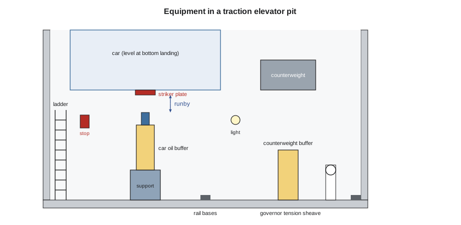
The pit is the bottom of the hoistway, and on a traction elevator it holds the equipment that deals with the end of travel and the bottom of the moving systems: the car and counterweight buffers, the governor tension sheave, the pit stop switches, the light, the ladder and the rail bases. On Quayside car 2, the pit work comes after the bottom rails are aligned, so that the buffers can be centred under the car and counterweight striker positions taken from the rails. This lesson explains what buffers do and the main types, how their stroke is related to speed, how they and the rest of the pit equipment are installed, and the safety of the work.
What a buffer does
A buffer is the device at the bottom of the hoistway that stops a car or counterweight that has gone past its normal limit of travel. If the car overruns the bottom landing, it lands on the car buffer. If the car overruns the top landing, the counterweight lands on the counterweight buffer, which stops the car from rising further. The buffer brings the moving mass to rest over a short distance at a controlled deceleration, so that the people in the car are not injured and the equipment is not damaged.
A buffer is not designed to stop a falling car. A car that is falling freely is stopped by its safeties gripping the rails, which is the subject of ELV-320, and the buffers deal with what is left: a car arriving at the bottom at or a little above its rated speed because something in the normal stopping system has failed. The code therefore sizes buffers for a striking speed related to the rated speed, not for free fall. The car also has terminal stopping devices that slow and stop it near the end of travel, and the buffers are the last line after those.
Types of buffers
There are two broad kinds. An energy-accumulating buffer stores the energy of the moving mass and gives some of it back: a coil spring, or an elastomer block such as polyurethane. An energy-dissipating buffer turns the energy into heat: the oil buffer, in which a plunger driven down into a cylinder forces oil through orifices that get smaller as the plunger goes in, giving a nearly constant deceleration. A spring in the oil buffer returns the plunger when the load comes off.
| Type | How it works | Where used |
|---|---|---|
| Spring buffer | Coil spring compresses and stores energy | Lower-speed elevators, up to the speed the code allows for spring buffers |
| Elastomeric buffer | Polyurethane or similar block compresses | Low-speed elevators and some counterweights |
| Oil buffer | Plunger forces oil through orifices; spring returns it | Any speed; required above the spring buffer speed limit |
The speed at which oil buffers become necessary has long been set at 1 m/s (200 ft/min) in North American codes. Above that, a spring buffer long enough to stop the car gently would be impractically long, and it would throw the car back up as the spring released. The Quayside passenger cars run at 2.5 m/s (500 ft/min) and have oil buffers under the car and counterweight. The service car, which runs slower, has the same type for parts commonality.
Stroke and speed
The stroke of a buffer is how far it compresses from first contact to fully compressed. The faster the striking speed, the longer the stroke must be for the same deceleration, and the relationship is the square of the speed. For an oil buffer, North American codes have long set the minimum stroke on the basis of the car striking at 115 percent of its rated speed with an average deceleration of no more than gravity. The stroke at that speed and deceleration comes from the ordinary motion equation:
# Minimum oil buffer stroke: 115 % of rated speed, average deceleration of 1 g
g = 9.81                              # metres per second squared
for rated in (1.0, 1.75, 2.5, 4.0):              # rated speed, m/s
    v = 1.15 * rated            # striking speed in m/s
    stroke = v ** 2 / (2 * g)         # m
print(f"rated {rated:>5} m/s: full stroke {stroke * 1000:6.0f} mm; reduced-stroke floor at half: {stroke * 1000 / 2:6.0f} mm")rated 1.0 m/s: full stroke 67 mm; reduced-stroke floor at half: 34 mm rated 1.75 m/s: full stroke 206 mm; reduced-stroke floor at half: 103 mm rated 2.5 m/s: full stroke 421 mm; reduced-stroke floor at half: 211 mm rated 4.0 m/s: full stroke 1078 mm; reduced-stroke floor at half: 539 mm
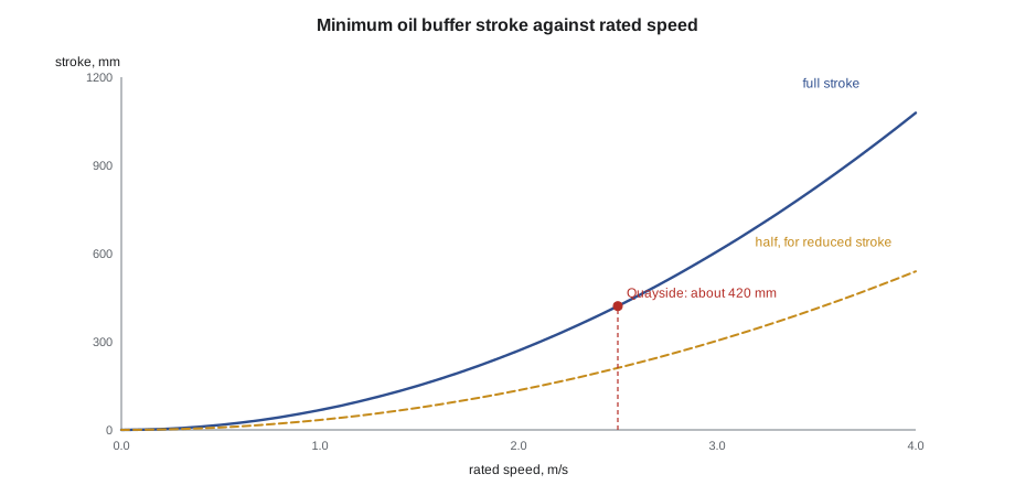
For the Quayside passenger cars, the full stroke works out to about 420 mm. The figure matches the long-standing code table for that speed. Where the elevator has an emergency terminal speed limiting device that guarantees a lower striking speed, the code allows a buffer with a reduced stroke, within limits; for speeds like Quayside's, the reduced stroke has traditionally been no less than half the full value. Reduced-stroke buffers are common on high-speed cars because they save pit depth. The Quayside layout uses full-stroke buffers, and the pit depth was set to suit.
Spring buffers have their own table of minimum strokes, much shorter, because they serve only the low speeds. Long-standing values are about 38 mm up to 0.5 m/s, 64 mm up to 0.75 m/s, and 102 mm up to 1 m/s. A spring buffer must also be strong enough that it does not go solid under a static load of twice the car and rated load, or twice the counterweight. These values are given here to show the pattern; the edition of the code in force sets the numbers for a particular unit.
Runby and the buffer position
When the car is level at the bottom landing, there is a gap between the striker plate under the car and the top of the car buffer. That gap is the bottom runby. It gives the car room to level and to stop normally without touching the buffer, and the code sets a minimum and a maximum for it. The counterweight has its own runby, measured with the car level at the top landing. The layout gives both runbys, and the buffer support height is chosen to produce them. Getting them right matters at both ends. Too little runby, and the car lands on its buffer in normal service. Too much, and the clearances when the car is on its compressed buffer, which set the refuge space in the pit and the clearances at the top, are no longer what the design assumed.
Counterweight runby has a second effect. With the car at the top landing, the counterweight is near the bottom of the pit. If the car overruns upward, the counterweight lands on its buffer and compresses it, and the car rises by the counterweight runby plus the buffer stroke. That rise has to fit within the overhead, and the code requires a clearance and a refuge space above the car top even then. The counterweight runby and buffer stroke at Quayside were therefore set on the layout together with the overhead in Lesson 3, and the crew sets them exactly.
Installing the buffers
Buffers are installed on supports: steel channels, pedestals or stands fastened to the pit floor, or on the pit floor itself for short buffers. The reactions table gives the force the buffer puts into the pit floor when the car or counterweight strikes it, and the pit slab is designed for it, so the buffers and supports are set exactly where the layout puts them.
- Position. Centre each buffer under its striker plate position, measured from the rails, so that the car or counterweight strikes it squarely. The car has not been built yet, so the striker position comes from the rail centre lines and the layout.
- Height. Set the buffer support height to give the layout runby, measured from the bottom landing benchmark with an allowance for the car not yet built, and record it.
- Plumb and level. An oil buffer must stand plumb, because its plunger moves in a straight line in its cylinder; a buffer out of plumb can bind as it compresses.
- Fastening. Anchor the supports and buffer bases with the fastenings on the details, torqued and recorded.
- Oil. Fill oil buffers with the oil the nameplate specifies, to the level marked, with the plunger fully extended, and check that the oil level gauge reads correctly.
- Switches. Where the design requires a switch to show that an oil buffer has returned to its fully extended position, fit and wire it as shown.
Each buffer carries a nameplate giving its stroke, its load rating and, for oil buffers, the oil type. Tamsin copies the nameplate data for each buffer into the job log and photographs the plates, because the acceptance inspector will check that the buffers match the design. At acceptance, oil buffers are tested by running the car onto them under conditions the code specifies, and the buffers must return to full extension afterwards.
The rest of the pit
The governor tension sheave keeps the governor rope tight. It hangs on the rope in the pit, held down by its own weight or a weight arm, and runs in a guide fixed to a rail or a bracket so that it can move up and down as the rope stretches. A switch opens the safety circuit if the sheave drops too far, which shows a broken or badly stretched rope. The governor and its rope belong to the safety system covered in ELV-320, but the tension sheave bracket is set during the pit work so that the rope will hang plumb from the governor at the top.
- Pit stop switches. At least one stop switch must be reachable from the pit access, so that a mechanic can stop the elevator before stepping in, and deep pits may need another reachable from the pit floor. Each is a red, manually operated switch that opens the safety circuit.
- Pit light and receptacle. A guarded light with its switch reachable from the pit access, and a ground-fault protected receptacle for tools.
- Pit ladder. A fixed ladder where the pit is deeper than the code allows without one, set clear of the car and counterweight paths and extending above the landing sill or with a grab bar.
- Counterweight guard. A screen in the pit, where the code requires one, to stop a person walking into the path of the counterweight.
- Rail base plates and drainage. The bottoms of the rail runs, and a sump or drain where the layout shows one, kept clear of oil and debris.
On a multi-car hoistway like Quayside's, the pits of adjacent cars are separated by a screen or partition where the code requires it, so that a mechanic in one pit cannot step into the path of the next car or its counterweight. The refuge space under each car is marked on the pit floor once the buffers are set.
Pit work safety
All of this is pit work, done at the bottom of an open hoistway that may still have rail work going on above. Nobody is in the pit while anything is happening above in that hoistway, and Lena records pit work on the access log. Oil buffers for a car like Quayside's are heavy enough that they are lowered into the pit with the hoist and a lift plan, never carried down the ladder. Buffer oil is kept in closed containers and spills are cleaned at once, because oil on the pit floor is a slip and fire hazard. No one stands on a buffer to reach anything, and no one stands under the counterweight once it is hung, even with the elevator out of service.
Once the car is running, entering the pit follows the entry procedure from ELV-110: stop switch, light, and a test that the car will not move before stepping in. During construction, before the car runs, the pit is still an open hole at the bottom of a shaft with work possible above it. The access log and the no-work-below-other-work rule are what keep it safe.
Common mistakes
MistakeThinking the buffer will stop a falling car.
InsteadBuffers stop an overrun at a speed related to rated speed; the safeties stop a free fall.
MistakeSetting the buffer support height by eye.
InsteadSet it to give the layout runby, measured from the landing benchmark, and record it.
MistakeLeaving an oil buffer unfilled until the end of the job.
InsteadFill to the nameplate level with the specified oil as soon as it is set, and check the gauge.
MistakeSetting a buffer off centre to clear a pit obstruction.
InsteadReport the obstruction; the buffer must sit under its striker.
MistakeWorking in the pit while rails are stacked above.
InsteadNo work below other work; schedule the pit for when the hoistway above is clear.
Summary and key terms
- Buffers stop an overrun car or counterweight at a controlled deceleration; safeties stop a free fall.
- Spring and elastomeric buffers store energy; oil buffers dissipate it and are required above the spring buffer speed limit.
- Oil buffer stroke has traditionally been based on 115 percent of rated speed at an average deceleration of 1 g.
- Runby is the gap between striker and buffer; it is set within code limits by the buffer support height.
- Buffers are centred, plumb, anchored, filled and recorded from their nameplates.
- The pit also holds the governor tension sheave, stop switches, light, ladder and guards.
- Buffer
- A device at the bottom of the hoistway that stops an overrunning car or counterweight.
- Oil buffer
- A buffer in which a plunger forces oil through orifices to dissipate energy.
- Stroke
- The distance a buffer compresses from first contact to fully compressed.
- Runby
- The gap between the striker and the buffer when the car is level at the terminal landing.
- Striker plate
- The plate under the car or counterweight that contacts the buffer.
- Governor tension sheave
- The weighted sheave in the pit that keeps the governor rope tight.
Practice problems
Work each problem on paper first, then reveal the answer to check.
What stops a freely falling car, and what does a buffer do?
Show answer
The safeties stop a falling car; the buffer stops an overrun at the end of travel.
What is the full oil buffer stroke for a rated speed of 1.75 m/s?
Show answer
About 206 mm.
Why must the counterweight runby be set exactly?
Show answer
The car rises by the counterweight runby plus buffer stroke if it overruns upward, and that must fit in the overhead with the required clearances.
Name four items besides buffers that are installed in the pit.
Show answer
Any four of: governor tension sheave, pit stop switch, light, receptacle, ladder, counterweight guard, rail base plates, sump.
Lesson quiz · 5 questions
Score 60% or more to complete this lesson.
Create a free account to save your progress, take quizzes and earn a certificate.