
ELV-120 · Lesson 2 of 12 · 18 min
Reading elevator layout drawings
The layout drawing is the most important document on an elevator installation. It shows where every part of the elevator goes in the hoistway, how big the hoistway must be to hold it, what the building must provide, and what forces the elevator puts into the building. It is drawn by the manufacturer or the elevator contractor's engineering department for one specific unit in one specific building, approved by the architect and structural engineer, and submitted with the permit application. On the first morning at Quayside, Ray spread the layout for car 2 across the gang box and told Tamsin that she would read it so many times she would be able to draw it from memory, and that until she could, she should not set a single bracket.
This lesson works through the Quayside layout sheet by sheet: the plan view, the elevation, the details, and the loads and reactions table. The aim is not to design an elevator but to read one, so that a mechanic can find any dimension on site, spot a conflict before it is built, and know which number to check when something does not fit.
What is on a layout set
A layout set for a traction elevator usually has three or four sheets. The plan view is a horizontal section through the hoistway, looking down, showing the car, the counterweight, the rails and brackets, the entrance, and the clearances between them. The elevation is a vertical section showing the pit, every landing, the overhead, the travel and the floor heights, with the rail bracket positions and the buffers. The details sheet shows the brackets, fastenings, entrances and machine supports at a larger scale. The general data block, often on the first sheet, lists the capacity, speed, travel, number of stops, code edition, machine type, roping, door type and the reactions the building must carry.
| Sheet | What a mechanic reads from it |
|---|---|
| General data | Capacity, speed, travel, stops, code edition, roping, machine and door type |
| Plan view | Clear hoistway, rail positions, distance between guides, car and counterweight position, clearances |
| Elevation | Pit depth, overhead, floor heights, bracket spacing, buffer positions, top and bottom of rails |
| Details | Bracket types, anchors and inserts, rail sizes, machine supports, entrance details |
| Reactions | Forces at the pit floor, at each bracket row and at the machine supports |
The plan view
The plan view is read from the front of the hoistway, which is the landing side. Its key reference line is the front wall line: the face of the hoistway wall at the landings, which is also the line the hoistway sills are set to. The other reference lines are the centre line of the car rails, which runs side to side through both car rail blades, and the centre line of the car, which runs front to back and usually lines up with the centre of the entrance. Almost every dimension on the plan is taken from one of these lines, and the plumb lines in Lesson 4 are set to reproduce them in the hoistway.
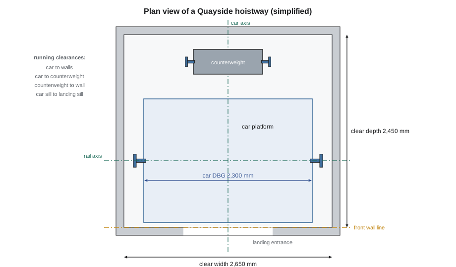
The distance between guides, abbreviated DBG, is the distance between the faces of the two rail blades, measured across the car or across the counterweight. It is one of the most important numbers on the drawing, because the car's guide shoes or roller guides are built for it. A car DBG that is too wide lets the car rattle side to side; too narrow, and the guides bind or wear quickly. The counterweight has its own DBG, much smaller, set by the counterweight frame width.
The plan also shows the running clearances: between the car and the hoistway walls, between the car and the counterweight, between the counterweight and the walls or a separator, and between the car sill and the landing sills. The code sets minimum values for each, and the layout designer has already allowed for them. The mechanic's job is to make sure the hoistway as built leaves room for them, which is what the survey in Lesson 3 checks. In a common hoistway like Quayside's, where four cars share one shaft, the plan view also shows the separator beams between cars and the divider screens that keep a mechanic on one car top from reaching into the path of the next car.
Reading the plan as a sum of parts
A useful habit is to add up the plan view across and front to back, and see how much space is left. Across the hoistway, the parts are the clearance at each side, the bracket and rail on each side, and the car between them. Front to back, they are the running clearance at the sill, the platform depth, the clearance between car and counterweight, the counterweight frame, and the clearance at the back. If the sum is larger than the clear hoistway, the elevator does not fit, and if it is much smaller, the layout may have been drawn for a different hoistway. The calculation below uses the Quayside car 2 layout, with illustrative clearances.
# Does the car 2 layout fit the clear hoistway? (illustrative clearances, mm)
clear_width, clear_depth = 2650, 2450        # from the layout: clear hoistway
across = {                       # side to side, left to right
    "left clearance to bracket": 25,
    "left bracket and rail": 150,
    "car between rail blades (car DBG)": 2300,
    "right bracket and rail": 150,
    "right clearance to bracket": 25,
}
front_back = {                   # front wall to back wall
    "sill running clearance": 30,
    "platform depth": 1650,
    "car to counterweight": 100,
    "counterweight frame and guides": 420,
    "counterweight to back wall": 200,
}
for name, parts, clear in (("width", across, clear_width), ("depth", front_back, clear_depth)):
    need = sum(parts.values())
print(f"{name}: parts add to {need} mm, clear is {clear} mm, spare {clear - need} mm")width: parts add to 2650 mm, clear is 2650 mm, spare 0 mm depth: parts add to 2400 mm, clear is 2450 mm, spare 50 mm
The output shows that the parts fill the width with nothing to spare and leave a little room front to back. That tells the crew where the tight dimension is: across the hoistway, where any wall that bellies in at a floor will push a bracket out of position. Ray marks the tight direction on the drawing with a highlighter before the survey begins, so that the survey team knows which readings matter most.
The elevation
The elevation is a vertical section through the hoistway. At the bottom is the pit, with its depth dimensioned from the lowest landing floor to the pit floor. At the top is the overhead, dimensioned from the top landing floor to the underside of the roof slab or the machine space above. In between, each landing is shown with its floor height, and the total travel is the distance from the lowest to the highest landing floor. For Quayside, the travel is 87 m (285 ft) over 30 floors, from the lobby to the 30th floor, at 3.0 m (10 ft) floor to floor throughout.
The elevation also shows the rail bracket rows, usually at each floor slab with any intermediate brackets between, the position of the car and counterweight buffers in the pit, the top and bottom of each rail run, and the positions of the machine and any sheaves at the top. On a machine-room-less unit like the Quayside passenger cars, the machine sits at the top of the hoistway on its own supports, and the controller sits in a cabinet at a landing, so the elevation shows both. The bottom of each rail run is shown resting on the pit floor or on a rail base plate, and the top is shown with a clearance below the overhead slab, which matters for building compression in Lesson 7.
| Elevation dimension | Quayside car 2 (from the layout) | Why it matters |
|---|---|---|
| Pit depth | 2.4 m (8 ft) | Buffers, refuge space and pit equipment must fit |
| Travel | 87 m (285 ft) | Sets rail quantity and the number of bracket rows |
| Overhead | 4.6 m (15 ft) | Room for the machine, top clearances and refuge on the car top |
| Floor to floor (typical) | 3.0 m (10 ft) | Sets bracket row spacing where brackets are at each slab |
| Top of rail below overhead slab | 150 mm (6 in) | Gap that allows the building to shorten without crushing the rails |
Details and fastenings
The details sheet shows each type of bracket used, with its size, the rail it carries, the fastening to the building and the fastening of the rail to the bracket. At Quayside there are three bracket types: a single car rail bracket fastened to the side wall of the hoistway where a car rail runs along a concrete wall, a counterweight bracket that spans between the rear wall and the counterweight rails, and a separator beam bracket where a rail runs on a steel beam between two cars. Each detail names the anchor or insert to be used, its size and its embedment or the torque it must be tightened to. These are not suggestions. An anchor of a different type, size or embedment is a different design, and it needs the engineer's approval before it goes in.
The details also show the rail clips: the small forgings that hold the rail foot to the bracket. On Quayside's high-rise cars, the drawing calls for sliding clips that let the rail move vertically relative to the bracket as the concrete building shortens, with fixed clips only at the bottom. Missing that detail, and using fixed clips throughout, would let the building's shortening load the rails in compression until they bowed.
Reactions and loads
The reactions table lists the forces the elevator puts into the building. The structural engineer uses it to design the pit slab, the walls, the inserts and the machine supports. The mechanic uses it to understand why a bracket or anchor is specified the way it is, and to check that the bearing points provided match what was designed for. Typical entries are the buffer reactions on the pit floor when the car or counterweight strikes the buffer, the horizontal rail forces at each bracket row from normal running, loading and safety application, and the vertical and horizontal reactions at the machine supports.
A mechanic does not recalculate these forces, which is engineering work signed and sealed by a professional engineer, but should be able to find them, read their units, and see when something on site does not match. At Quayside, the insert type on two floors did not match the details sheet, and Lena sent the question to the general contractor and the engineer of record before the crew went past those floors.
Revisions and conflicts
Layout drawings change during a job. The title block carries a revision table listing every change, its date and who approved it, and each changed area on the drawing is marked with a revision cloud and a triangle. Before using a drawing, Ray checks the revision number against the latest issued, and he keeps superseded prints out of the site office. When the drawing and the building disagree, the mechanic does not choose. The conflict is written up with measurements and photographs and sent through the superintendent. Typical conflicts are a wall poured out of plumb, an opening in the wrong place, a beam where the counterweight should run, an insert missing, or a pit poured shallow. Some can be absorbed by adjustment within the drawing's tolerances; others need a revised layout or building work.
Small symbols carry a lot of meaning on a layout. A centre line is drawn as a long-short dash. A dimension with a plus-or-minus tolerance means the hoistway may vary by that much; a dimension marked minimum means it may be larger but never smaller. Hidden parts are dashed. An arrow with a letter and number points to a section or detail on another sheet. Tamsin built a one-page key from the Quayside set in her first week and taped it inside her log book.
Common mistakes
MistakeMeasuring from the hoistway wall instead of the reference lines.
InsteadWork from the front wall line and the rail centre line as the drawing does; the wall itself may not be where the drawing says.
MistakeSubstituting a different anchor because the specified one is out of stock.
InsteadAn anchor of a different type or embedment is a design change and needs the engineer's approval.
MistakeUsing fixed rail clips throughout a high-rise.
InsteadFollow the details sheet; sliding clips let the building shorten without loading the rails.
MistakeAssuming the general data block matches the permit.
InsteadCheck the code edition, capacity and speed against the approved permit drawings.
MistakeResolving a drawing conflict on site by eye.
InsteadMeasure, photograph and send it through the superintendent; do not build around it.
Summary and key terms
- The layout drawing fixes the position of every part of the elevator for one unit in one building.
- The plan view is dimensioned from the front wall line and the rail and car centre lines.
- The distance between guides (DBG) is measured between rail blade faces and must match the car or counterweight guides.
- The elevation gives the pit depth, travel, overhead, floor heights, bracket rows and buffer positions.
- The details sheet specifies brackets, anchors and clips; changes need engineering approval.
- The reactions table lists forces on the building; mechanics read it but do not redesign it.
- Plan view
- A horizontal section through the hoistway, looking down.
- Elevation
- A vertical section through the hoistway showing the pit, landings and overhead.
- Front wall line
- The reference line along the face of the hoistway wall at the landings.
- Distance between guides (DBG)
- The distance between the blade faces of a pair of rails.
- Running clearance
- The gap the code requires between moving parts and anything they pass.
- Reaction
- A force the elevator puts into the building at a support.
Practice problems
Work each problem on paper first, then reveal the answer to check.
What reference line is the plan view usually dimensioned from at the front?
Show answer
The front wall line at the landings.
What does DBG stand for and where is it measured?
Show answer
Distance between guides, between the faces of the two rail blades.
The parts across a hoistway add to 2,610 mm and the clear width is 2,650 mm. How much is spare?
Show answer
40 mm.
An insert on site does not match the details sheet. What happens next?
Show answer
Measure and photograph it, and send it through the superintendent to the general contractor and engineer before building past it.
Lesson quiz · 5 questions
Score 60% or more to complete this lesson.
Create a free account to save your progress, take quizzes and earn a certificate.