
ELV-120 · Lesson 5 of 12 · 18 min
Guide rail types and materials
Guide rails are the steel tracks that keep the car and the counterweight on their paths up and down the hoistway. They do three jobs. They guide: the car's guide shoes or roller guides run on them, and the straightness of the rails sets the ride quality. They hold: when the car's safeties set, they grip the car rails and bring the car to a stop, so the rails and their brackets must take the full braking force. And they steady: they resist the side forces from loading the car off centre, from the ropes and from the building moving in wind or an earthquake. A rail that is the wrong size, damaged or poorly joined fails at one of these jobs.
This lesson describes the standard T-section rail, its sizes and designations, the joints and fishplates that make a continuous rail from individual lengths, how rails are chosen, and how they are received, stored and handled on site before they go up the hoistway. Setting and aligning them is Lesson 7.
The T-section rail
Almost all modern elevator rails are T-section steel rails made for the purpose. The rail has three parts. The blade, also called the head or tongue section, is the upright part of the T that the guides run on; its tip and both sides are the guiding faces. The foot, or base, is the wide flat flange at the bottom of the T, which is clamped to the brackets with clips. The web is the short section where the blade meets the foot. The back of the foot is machined flat where the fishplates bear on it.
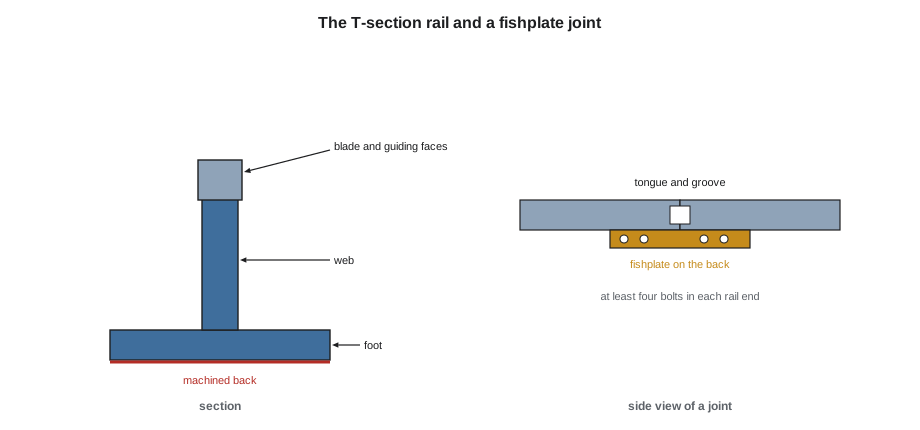
The guiding faces of a rail for passenger service are machined, which means they are cut to an accurate size and a smooth finish after the rail is rolled. The machining matters because the guide shoes and roller guides bear on these faces, and because the safety jaws grip them. Damage to a machined face, such as a dent from a dropped bracket or a burr from careless handling, can be felt in the ride and can affect the safety's grip, and it has to be dressed out with a file before the rail goes in. Rails for low-speed counterweights and some freight elevators may be cold drawn rather than machined, and some counterweights run on formed sheet steel rails, which are lighter and cheaper but suited only to limited loads and speeds.
Rail sizes and designations
Rails supplied in Canada for current installations are usually made to the international rail standard, which names each rail by the letter T and the width of its foot in millimetres, followed by a suffix for the type of manufacture: T89/B, for example, is a machined rail with an 89 mm foot. Common sizes run from T70 up to T140, and larger rails come in more than one weight for the same foot width. Older North American installations, and rails made to the ASME and CSA tables, are named by their nominal weight per foot: 8, 11, 12, 15, 18.5, 22.5 and 30 lb rails. A mechanic will meet both systems on service work, and needs to know which is in front of him or her before ordering a replacement length.
Metric rails come in standard lengths of 5 m, and each length is machined at the ends with a tongue on one end and a matching groove on the other so that the lengths fit together in line. At Quayside, the passenger car rails are T127-1/B and the counterweight rails are T89/B. A 5 m length of the car rail weighs a little over 100 kg, which is why rails are never lifted by hand up the hoistway.
| Use at Quayside | Rail | Mass of one length (approximate) |
|---|---|---|
| Passenger car rails | T127-1/B, 5 m lengths | 110 kg (240 lb) |
| Passenger counterweight rails | T89/B, 5 m lengths | 62 kg (128 lb) |
| Service car rails | T127-1/B, 5 m lengths | 110 kg (240 lb) |
Joints and fishplates
A rail run is built from many lengths, joined end to end. At each joint, the tongue of one length fits into the groove of the next, which lines up the blades, and a fishplate is bolted across the joint to the back of both rail feet. The fishplate is a thick steel plate, as wide as the back of the rail, drilled to match the holes in the rail ends. It holds the rails in line, transfers bending from one length to the next, and keeps the joint from opening. The code sets a minimum number of bolts in each rail end and a minimum fishplate thickness and bolt size for each rail weight, and the fishplates supplied with the rails meet them.
| Nominal rail weight | Minimum fishplate thickness | Minimum bolt diameter |
|---|---|---|
| 8 lb | 9/16 in | 1/2 in |
| 11, 12 and 15 lb | 11/16 in | 5/8 in |
| 18.5 and 22.5 lb | 13/16 in | 3/4 in |
| 30 lb | 15/16 in | 3/4 in |
The joint is the weak point of a rail and the place where most ride problems start. If the tongue does not seat fully in the groove, the blades step at the joint. If the fishplate bolts are not tight, the joint can open as the building moves. If there is dirt or a burr between the fishplate and the rail back, the rail ends can tilt. The joints are made carefully, cleaned before assembly, and checked again during alignment in Lesson 7. The joint positions on the left and right car rails are also staggered so that the car's guides do not pass two joints at the same moment, which would turn a small step into a noticeable bump.
How rails are chosen
Choosing the rail size is engineering work done by the elevator designer, not a decision made on site. The size depends on the mass of the car and its rated load, how the load may be placed in the car, the type of safety and the forces it applies to the rails when it sets, the bracket spacing, the speed, and the seismic forces the building may see. Heavier loads and wider bracket spacing need bigger rails; closer brackets allow smaller rails. That is why the rail size and the bracket spacing on the layout belong together, and why changing one without the other is not allowed.
The code governs the result. Rails must be steel, or another metal that meets the code's strength and deflection requirements; cast iron is not permitted. They must be strong enough, with the code's factor of safety, for the loads they see, and stiff enough that their deflection under the safety forces stays within the code's limit. Each rail run must extend far enough at the top and bottom that the car and counterweight guides can never run off the ends of the rails, even when the car or counterweight is on its fully compressed buffer or has run up to the top of its travel.
Rail run length and quantity
Each rail run goes from the pit floor, or from a rail base plate on the pit floor, to a point just below the overhead, leaving the gap at the top that the layout shows. The number of lengths in each run comes from the run length divided by the standard length, with the last length cut to fit. For a car with two car rails and two counterweight rails, the order is four times that, plus spares. The code below works out the run length and quantities for Quayside car 2 from its elevation, as an order check.
# Rail quantity check for Quayside car 2 (from the elevation)
import math
pit, travel, overhead, top_gap = 2.4, 87.0, 4.6, 0.15     # m
std = 5.0                                  # standard rail length, m
run = pit + travel + overhead - top_gap      # pit floor to top of rail
full = math.floor(run / std)
cut = run - full * std
print(f"rail run length: {run:.2f} m")
print(f"each run: {full} full lengths and one cut length of {cut:.2f} m")
for name, mass in (("car rail", 22.0), ("counterweight rail", 12.4)):
    per_run = run * mass
print(f"{name}: {2 * per_run:,.0f} kg for the pair of runs")rail run length: 93.85 m each run: 18 full lengths and one cut length of 3.85 m car rail: 4,129 kg for the pair of runs counterweight rail: 2,327 kg for the pair of runs
The pair of car rails for car 2 alone weighs more than four tonnes, and the counterweight rails add more than two. Every length has to be lifted into the hoistway, stood on the length below and joined, so material handling is a large part of the rail stage. The masses per unit length in the code are approximate catalogue values for these rails.
Receiving, storing and handling rails
Rails arrive on site in bundles, usually by truck, and the first inspection happens before the driver leaves. The crew checks the count and sizes against the packing list, checks for bundles that have been bent or dropped, and looks at the ends for damaged tongues and grooves. A bent rail cannot be used as a guiding rail; it goes back.
- Store rails flat on level timbers spaced closely enough that the rails do not sag, off the ground, in a place where they will not be run over.
- Keep the protective oil coating on and the bundles covered, because rust on a machined face has to be cleaned off before installation.
- Keep the fishplates and bolts for each size together and labelled, so that the right ones go with each rail.
- Never drag a rail across another, stand a rail on its machined end, or use a rail as a lever or a support for other work.
- Move rails with lifting equipment and a plan, with tag lines to control the ends; hands stay clear of the ends and the fishplate holes, which are pinch points.
Rails also need lubrication if the car runs on sliding guide shoes. The lubricant must be one the safety manufacturer accepts, because grease or oil of the wrong type on the blade can change how the safety grips. Cars on roller guides, like the Quayside passenger cars, run on dry rails, and on those cars any oil on the blades is cleaned off.
Checking a rail before it goes up
Before each length leaves the laydown area, the crew gives it a final look, because a defect found on the ground costs minutes and the same defect found halfway up the hoistway costs a morning. Tamsin's routine at Quayside takes about two minutes a rail. She sights along the blade from one end to check that the length is straight, with no kink or twist, and lays a straightedge along the blade tip near each end, where rails are most often bent in handling. She checks the tongue and the groove for dents and burrs, because a damaged tongue will not seat and leaves a step at the joint. She runs a gloved hand along the machined faces to find nicks, marks them with chalk, and dresses them with a file before the rail is lifted. She checks that the fishplate holes are clean and that the correct fishplate and its bolts are bundled with the length. And she wipes off any rust bloom on the machined faces, which on a rail stored outside through a wet Pacific Northwest spring can appear within a week.
Each rail is then marked with the car number, the rail position, such as car 2 left, and its number in the run counted from the pit. The marks go on the back of the foot, where they will not be seen in the finished hoistway. Marking the run order matters for the cut lengths: the bottom length is a full length, the top length is cut, and a cut length in the middle of a run would put every joint above it in the wrong place relative to the brackets. When a rail is rejected, it is tagged, set aside away from the good stock, and listed on the delivery report so that a replacement is ordered at once.
Common mistakes
MistakeOrdering a replacement rail by appearance.
InsteadIdentify the rail by its designation or nominal weight, and check the foot width and blade size before ordering.
MistakeInstalling a rail with a dented blade.
InsteadDress out damage on the guiding faces before installation, or reject the rail if it cannot be dressed.
MistakeLeaving the fishplate bolts snug for later.
InsteadTighten fishplate bolts to the specified torque as each joint is made, and recheck during alignment.
MistakeJoints on both car rails at the same height.
InsteadStagger the joints as the layout shows so that the guides do not pass two joints at once.
MistakeGreasing the rails on a car with roller guides.
InsteadRoller guides run on dry rails; use only lubricant the safety manufacturer accepts where sliding guides are used.
Summary and key terms
- Guide rails guide the car and counterweight, take the safety stopping force and resist side loads.
- A T-section rail has a blade with machined guiding faces, a web and a foot clamped to the brackets.
- Rails are named by T-number and foot width in the international system, or by nominal weight per foot in the ASME tables.
- Fishplates join the lengths; minimum plate thickness, bolt size and bolt count are set by the code.
- Rail size goes with bracket spacing and is chosen by the designer; it is not changed on site.
- Rails are inspected on delivery, stored flat and covered, and handled with equipment and a plan.
- Guide rail
- A steel track that guides the car or counterweight and takes the safety stopping force.
- Blade
- The upright part of a T-section rail that the guides run on.
- Foot
- The wide base of a T-section rail, clamped to the brackets.
- Fishplate
- A steel plate bolted across a rail joint to the backs of both rail feet.
- Tongue and groove
- The machined ends of each rail length that line up adjoining lengths.
- Rail run
- The full line of joined rail lengths from the pit to the top of the hoistway.
Practice problems
Work each problem on paper first, then reveal the answer to check.
Name the three jobs of a guide rail.
Show answer
Guiding the car or counterweight, taking the safety stopping force, and resisting side forces.
What does the B in T89/B indicate?
Show answer
That the rail is machined.
A rail run is 93.85 m long with 5 m rails. How many full lengths, and how long is the cut length?
Show answer
18 full lengths and a cut length of 3.85 m.
Why are the joints on the two car rails staggered?
Show answer
So the guides do not pass two joints at the same moment.
Lesson quiz · 5 questions
Score 60% or more to complete this lesson.
Create a free account to save your progress, take quizzes and earn a certificate.