
ELV-120 · Lesson 3 of 12 · 18 min
Hoistway survey and as-built checks
No hoistway is built exactly as drawn. Concrete forms shift, walls belly between floors, slabs are poured a little high or low, inserts move when the concrete is vibrated, and the general contractor's own tolerances allow some variation. The layout drawing assumes a perfect shaft. The survey finds out what was actually built, so that the elevator can be fitted into the real hoistway rather than the imaginary one. At Quayside, the survey of the car 2 hoistway took Ray and Tamsin a day and a half, and it found two problems that would have cost a week each if they had been discovered with the rails half set.
This lesson covers what is measured, how it is measured safely, how the readings are recorded and checked, and what happens when the hoistway is out of tolerance. Plumbing the hoistway, which sets the permanent reference lines for the rails, is the next step and the subject of Lesson 4. In practice the two overlap: a first set of lines is often hung for the survey and then adjusted to become the plumb lines.
What the survey measures
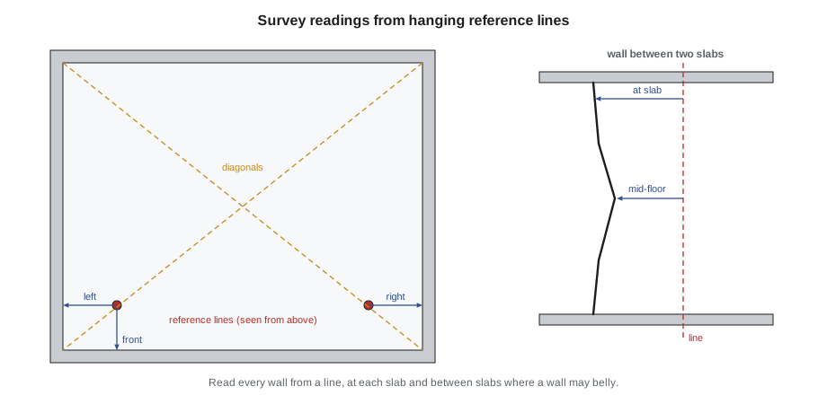
The survey compares the hoistway to every dimension on the layout that the elevator depends on. At each floor, and at points between floors where walls may belly, the crew measures the clear width and depth of the hoistway, the position of each wall relative to the reference lines, and the size and position of the landing opening. In the pit, they measure the depth from the lowest landing, the levelness of the pit floor, the position of any sump, and whether the pit is dry. At the top, they measure the overhead from the top landing to the underside of the slab or beams, and the position of the hoist beam and any machine supports. Along the way they check the bracket bearing points: whether every insert or plate is there, where it is, and whether it is the type the details sheet calls for.
| Item | Measured at | Compared with |
|---|---|---|
| Clear width and depth | Each floor and mid-floor | Plan view clear hoistway and its tolerance |
| Wall positions from the reference lines | Each floor | Plan view, to find bellied or leaning walls |
| Square of the hoistway | Top, bottom and some floors | Equal diagonals |
| Floor-to-floor heights | Each landing | Elevation |
| Pit depth and pit floor level | Pit | Elevation and buffer layout |
| Overhead | Top landing | Elevation |
| Landing openings | Each landing | Entrance details: width, height and position from the car centre line |
| Bearing points and inserts | Each bracket row | Details sheet: type, position and count |
Reference lines and benchmarks
Every measurement in the survey is taken from a reference, never from one wall to another alone, because if both walls lean the same way the width can look correct while the hoistway is far out of plumb. Horizontally, the references are temporary lines hung down the hoistway, usually two or four wires or laser lines set roughly where the plumb lines will go. Vertically, the reference is a benchmark: an elevation mark the general contractor's surveyor has set on each floor, usually 1 m (4 ft) above the finished floor level. Floor heights and pit depth are measured from these marks, not from the slab surface, because the slab at an elevator landing is often finished later with a topping or a floor finish.
The finished floor matters more than the slab because the hoistway sill must be set flush with the finished floor, and the car must level to the sill. A slab poured 20 mm (3/4 in) low with a floor finish to come will look like a problem if measured at the slab, and will not be one. A slab poured 20 mm (3/4 in) high with a finish still to go on top is a real problem. Lena gets the benchmark list and the finish schedule from the general contractor before the survey starts.
Doing the survey safely
A survey means working at open landings and in the hoistway, usually before any permanent platform is installed. Northcrest does the upper floors from the temporary work platform hung from the hoist beam, with both workers tied off to the lifelines on their separate anchor beam, and the lower floors from the landings through the barricade hatches. At each landing, the worker clips to the landing anchor before opening the hatch, opens only one hatch at a time, measures without leaning past the edge, and closes and latches the hatch before moving to the next floor. A tape is never held out over the hoistway by hand alone; the end is clipped to the line or to a hook on a pole.
The pit survey is done last, or at a time when nobody is working above, under the no-work-below-other-work rule. The pit is checked for water and debris first. At Quayside, the car 2 pit had 150 mm (6 in) of rainwater in it at turnover, which the general contractor pumped out before the crew went in. Laser instruments add one more hazard: a Class 2 or 3R laser beam can injure an eye if someone looks into it, so the beam is kept below eye level where possible, and the crew warns the other trades on site when it is running.
Recording the readings
The survey is recorded on a sheet with one row per reading position, from the pit to the top. At Quayside, each row has the floor, the benchmark elevation, the distance from each reference line to the side walls and the front wall, the calculated clear width, the opening width and position, and a note of the inserts at that row. The sheet is filled in on the platform in pencil, transcribed into a spreadsheet that evening, and checked the next morning before any further work. Tamsin learned to read each measurement back aloud before writing it, because a transposed digit in a survey becomes a bracket in the wrong place.
Once the readings are in, the useful numbers are the extremes. The minimum clear width over the full height is what the elevator must fit in; the floor where it occurs is the tight floor. The largest deviation of each wall from its reference line shows how far the wall is out of plumb. The code below takes the side-wall readings for car 2 and finds the tight floor and the worst wall.
# Car 2 survey: distance from the reference lines to each side wall (mm)
# Reference lines are 2400 mm apart; clear width = left + lines + right
ref_gap = 2400
readings = {      # floor: (left line to left wall, right line to right wall)
    "pit": (130, 128), 2: (127, 130), 6: (124, 133), 10: (121, 135),
    14: (118, 138), 18: (96, 138), 22: (116, 140),
}
need = 2650     # minimum clear width from the layout
tol = 25       # plus tolerance from the layout; minus tolerance is zero
widths = {f: round(l + ref_gap + r, 2) for f, (l, r) in readings.items()}
tight = min(widths, key=widths.get)
for f, w in widths.items():
    flag = "UNDER" if w < need else ("over tolerance" if w > need + tol else "ok")
    print(f"floor {str(f):>3}: clear width {w} mm  {flag}")
print(f"tight floor: {tight} at {widths[tight]} mm (need at least {need})")
left = [l for l, _ in readings.values()]; right = [r for _, r in readings.values()]
print(f"left wall varies by {round(max(left) - min(left), 2)} mm, right wall by {round(max(right) - min(right), 2)} mm")floor pit: clear width 2658 mm ok floor 2: clear width 2657 mm ok floor 6: clear width 2657 mm ok floor 10: clear width 2656 mm ok floor 14: clear width 2656 mm ok floor 18: clear width 2634 mm UNDER floor 22: clear width 2656 mm ok tight floor: 18 at 2634 mm (need at least 2650) left wall varies by 34 mm, right wall by 12 mm
The readings tell a clear story. The left wall drifts steadily inward from the pit to floor 14, which is a lean, and then jumps in at floor 18, which is a local problem. The right wall drifts slowly outward over the full height. The tight floor is 18, where the clear width is below the layout minimum. When Ray went back to floor 18 with a straightedge, he found a form blowout repaired with a thick patch of concrete that stood proud of the wall. That is a building problem, and the general contractor ground it back before the brackets went in. The lean of the left wall was within what the brackets could absorb, and it went into the plumbing decision in Lesson 4.
Square, openings and heights
A hoistway can be the right width and depth and still be twisted: a parallelogram rather than a rectangle. The check is to measure both diagonals, corner to corner, at the top, the bottom and some floors between. Equal diagonals mean the hoistway is square at that level. A difference means it is skewed, and a difference that changes with height means the hoistway is twisted. A twist matters most for the entrances, because every hoistway sill must be parallel to the front wall line and to the car sill.
Landing openings are checked for width, height and position. Their position is measured from the car centre line, because the entrance frames must line up with the car door, and an opening poured 50 mm (2 in) to one side may need a larger rough opening or a modified frame. Floor-to-floor heights are measured from benchmark to benchmark, and the total compared with the travel on the drawing. At Quayside, the total travel to the 22nd floor came out 12 mm (1/2 in) longer than the drawing, which is normal and is taken up later in the hoistway wiring and the landing positions in the controller.
Pit and overhead
The pit depth is the distance from the lowest landing finished floor to the pit floor. It must be at least what the layout calls for, because the buffers, the buffer supports, the governor tension sheave, the refuge space under the car and the clearances when the car is on its compressed buffers all have to fit. A pit poured shallow is one of the most expensive problems on an elevator job, because it can mean breaking out the pit slab, changing to a buffer with a shorter stroke where the code allows, or redesigning the pit equipment. The pit floor is also checked for level at the buffer positions, and for a sump or drain where the layout shows one.
The overhead is the distance from the top landing finished floor to the lowest point of the structure above. It must leave room for the car, the car top equipment, the clearances and refuge space on the car top when the counterweight is on its compressed buffer, and on a machine-room-less unit, the machine itself. A beam that hangs lower than the drawing shows, or a sprinkler pipe run through the top of the hoistway, can take the overhead below what the layout needs. At Quayside the top of the hoistway was not poured yet, so the overhead survey for car 2 was scheduled for when the roof slab was cast.
When the hoistway is out of tolerance
A survey that finds a problem produces a written report. It names the problem, gives the measurements and the drawing values, includes photographs, and states what the elevator crew needs: a wall ground back, an insert added, a pit deepened, or a decision from the engineer. The report goes through the superintendent to the general contractor, and a copy goes in the job file. Small deviations that the elevator can absorb, such as a wall that leans within the adjustment range of the brackets, are recorded but do not need building work. The plumbing decision then sets the rail lines to make the best use of the space that is there.
Ray's rule is that the survey report goes out the same day. A problem found on Monday and reported on Monday can be fixed by the general contractor's crew on Wednesday, before the elevator crew needs that floor. The same problem reported on Friday can hold up the job for a week.
Common mistakes
MistakeMeasuring wall to wall instead of from a reference line.
InsteadTwo walls leaning the same way look fine wall to wall; measure each wall from a hanging reference.
MistakeMeasuring heights from the slab.
InsteadMeasure from the benchmarks and allow for the floor finish to come.
MistakeLeaning out of an open hatch to read a tape.
InsteadTie off before opening the hatch and clip the tape end to the line or a pole.
MistakeSurveying the pit while others work above.
InsteadDo the pit when nothing is happening above in that hoistway.
MistakeWaiting until the end of the week to report a problem.
InsteadSend the report the same day, with measurements and photographs.
Summary and key terms
- The survey compares the hoistway as built with every dimension the elevator depends on.
- Measurements are taken from hanging reference lines and floor benchmarks, never wall to wall alone.
- The tight floor is the one with the smallest clear dimension; the elevator must fit there.
- Equal diagonals show a square hoistway; changing diagonals show a twist.
- Pit depth and overhead must be at least the layout values, and a shallow pit is a costly problem.
- Out-of-tolerance findings are reported in writing the same day through the superintendent.
- Survey
- Measurement of the hoistway as built, compared with the layout.
- As-built
- A record of what was actually built, as opposed to what was drawn.
- Benchmark
- An elevation mark on each floor, set by the building surveyor, used as the vertical reference.
- Tight floor
- The floor with the smallest clear hoistway dimension.
- Bellied wall
- A wall that bulges into the hoistway between two floor slabs.
- Twist
- A hoistway whose skew changes with height, shown by diagonals that change.
Practice problems
Work each problem on paper first, then reveal the answer to check.
Reference lines are 2,400 mm apart; at floor 9 the left reading is 120 mm and the right 128 mm. What is the clear width?
Show answer
2,648 mm.
Why are heights measured from benchmarks rather than the slab?
Show answer
The landing slab may receive a finish later, and the sill and car level to the finished floor.
The diagonals at the pit are equal, but at floor 20 they differ by a noticeable amount. What does that suggest?
Show answer
The hoistway is twisted, square at the bottom and skewed higher up.
What goes in a survey problem report?
Show answer
The problem, measured and drawing values, photographs and what the crew needs, sent the same day through the superintendent.
Lesson quiz · 5 questions
Score 60% or more to complete this lesson.
Create a free account to save your progress, take quizzes and earn a certificate.