
ELEC-420 · Lesson 9 of 12 · 25 min
Electrical safe work practices: shock, arc flash and lockout
Troubleshooting and commissioning expose electricians to more electrical hazards than almost any other work, because they often involve working near energized equipment, testing live circuits and energizing systems for the first time. Every year, electricians are killed or seriously injured by electric shock and arc flash, and many of these incidents occur during testing and troubleshooting, often to experienced workers who took a shortcut. This lesson covers the hazards of shock, arc flash and arc blast, the hierarchy of risk controls, establishing an electrically safe work condition with lockout and tagout, justifying and planning energized work, approach boundaries, arc flash risk assessment and labels, personal protective equipment, and the human factors that lead good electricians into bad situations.
Electrical hazards
Electric shock occurs when current passes through the body. Its effects depend on the current, its path and its duration: around 1 mA is perceptible, about 10 to 20 mA can cause loss of muscle control so the victim cannot let go, and around 50 to 100 mA through the chest can cause ventricular fibrillation, which is fatal without rapid defibrillation. Body resistance varies widely, from many thousands of ohms with dry skin to under 1,000 Ω with wet skin or broken skin, so even 120 V circuits can be lethal. Burns from current flow damage tissue internally along the current path.
An arc flash is the release of energy from an electric arc through air between conductors or to ground, caused by a fault, a dropped tool, a failed component or an incorrect test. Arc temperatures can reach about 20,000 °C, several times the surface temperature of the sun, producing intense heat and light that cause severe burns at a distance and ignite clothing. The arc vaporizes copper, which expands roughly 67,000 times in volume, creating an arc blast: a pressure wave that throws workers, ruptures eardrums and propels molten metal and shrapnel. Incident energy, measured in calories per square centimetre (cal/cm²), describes the thermal energy at a working distance; about 1.2 cal/cm² can cause a second-degree burn on bare skin.
Worked problem
Why low voltage can kill
A worker with wet hands contacts 120 V and a grounded surface. If total body resistance is 1,000 Ω, estimate the current and its likely effect. What if resistance were 100,000 Ω with dry skin?
Show solution
- Wet: I = 120 / 1,000 = 0.12 A = 120 mA.
- 120 mA through the chest is in the range that can cause ventricular fibrillation.
- Dry: I = 120 / 100,000 = 1.2 mA, perceptible but usually not dangerous.
- Skin resistance can drop suddenly when skin is wet, sweaty or broken, or when contact is firm over a large area.
- Treat every circuit as potentially lethal and control exposure rather than relying on skin resistance.
Answer: About 120 mA, potentially fatal, with wet skin; about 1.2 mA with dry skin.
The hierarchy of risk controls
Safety standards require employers to manage electrical risk using the hierarchy of controls, from most to least effective:
- Elimination: remove the hazard, most importantly by de-energizing equipment and establishing an electrically safe work condition.
- Substitution: reduce the hazard, for example by using lower-voltage control circuits or current-limiting devices.
- Engineering controls: isolate people from the hazard, such as remote racking devices, infrared windows, arc-resistant switchgear, finger-safe components and permanently installed absence-of-voltage testers.
- Awareness: signs, labels and barriers.
- Administrative controls: procedures, training, permits and supervision.
- Personal protective equipment: the last line of defence, which reduces injury when other controls fail but does not prevent the incident.
The hierarchy explains why the first question in any task is whether it can be done de-energized, and why PPE is never a substitute for safe procedures.
In Canada, CSA Z462 Workplace electrical safety, harmonized with NFPA 70E, sets out the hierarchy of risk controls, risk assessment procedures, approach boundaries and PPE requirements, and provincial occupational health and safety regulations make employers responsible for safe work procedures and worker training.
Establishing an electrically safe work condition
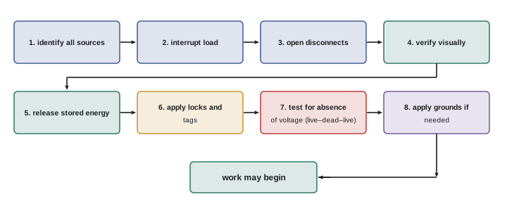
An electrically safe work condition (ESWC) exists when conductors and circuit parts have been disconnected from all sources, locked and tagged out, tested to verify the absence of voltage, and grounded where induced voltages or stored energy could be present. The process typically includes:
- Identify all possible sources of supply using up-to-date drawings, including backfeeds from generators, PV systems, UPS units, capacitors and control power from other panels.
- Interrupt the load current and open the disconnecting devices.
- Visually verify, where possible, that all blades are open or breakers withdrawn.
- Release stored energy: discharge capacitors, block or release mechanical energy such as springs and raised parts.
- Apply lockout devices and tags according to the written procedure, with each worker applying a personal lock.
- Test for absence of voltage with an adequately rated test instrument, using the live–dead–live method on each phase-to-phase and phase-to-ground combination.
- Apply temporary protective grounds where conductors could become energized by induction or accidental re-energization, especially on medium-voltage systems.
Testing for absence of voltage is itself energized work until proven otherwise, and it requires appropriate PPE.
When energized work is justified
Work on or near energized parts is permitted only when de-energizing would introduce additional or increased hazards (such as shutting down life-support equipment or ventilation in a hazardous location) or is infeasible because of equipment design or operational limitations, such as diagnostic testing that can only be done with the circuit energized. Inconvenience or production pressure is not a justification. Troubleshooting and testing are among the legitimate reasons, because many faults can only be found with voltage present, but the scope should be limited to the testing itself, not repairs. Energized work beyond diagnostic testing typically requires an energized electrical work permit, approved by management, describing the task, the justification, the risk assessment, the approach boundaries, the PPE and the safe work practices to be used.
Approach boundaries
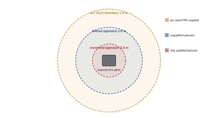
Shock risk assessment defines approach boundaries around exposed energized parts:
- Limited approach boundary: unqualified persons may not cross it unless escorted and informed by a qualified person.
- Restricted approach boundary: only qualified persons with appropriate shock protection, insulating gloves and tools, may cross it, and only with a plan.
For 151 to 750 V systems, NFPA 70E and CSA Z462 tables give a limited approach boundary of about 1.0 m (3 ft 6 in) for fixed circuit parts and a restricted approach boundary of about 0.3 m (1 ft). Arc flash risk assessment defines a separate arc flash boundary: the distance at which incident energy falls to 1.2 cal/cm², inside which anyone must wear arc-rated PPE. The arc flash boundary is often larger than the shock boundaries, sometimes several metres for large switchgear.
Arc flash risk assessment and labels
Arc flash risk assessment determines whether an arc flash hazard exists, the likelihood and severity of injury, and the protective measures needed. It can use an incident energy analysis, a calculation based on available fault current, protective device clearing time, working distance and equipment configuration (commonly using IEEE 1584 methods, as introduced in ELEC-320), or the PPE category tables in the standards, which apply only within their stated conditions of fault current and clearing time. Equipment that is likely to be examined, adjusted, serviced or maintained while energized must be labelled with information such as the nominal voltage, arc flash boundary and either the incident energy and working distance or the PPE category. Labels must be kept current: changes in the utility supply, transformer replacements or protective device settings can change incident energy significantly. The likelihood of an arc flash depends on the task and the equipment condition: operating a properly installed and maintained breaker with the door closed carries much less risk than racking a breaker, removing covers or testing inside an open enclosure.
Personal protective equipment
Arc-rated PPE is selected to have an arc rating at least equal to the incident energy at the working distance. Arc-rated clothing, face shields or arc flash suit hoods, balaclavas, hearing protection and leather or rubber insulating gloves with leather protectors protect against thermal burns, while safety glasses protect the eyes. PPE categories group requirements: for example, category 1 requires a minimum arc rating of 4 cal/cm², category 2 8 cal/cm², category 3 25 cal/cm² and category 4 40 cal/cm². Shock protection uses rubber insulating gloves of a class rated for the voltage (class 00 up to 500 V AC, class 0 up to 1,000 V AC), inspected and air-tested before each use and electrically tested at regular intervals, along with insulated tools and insulating mats or blankets. Everyday clothing of synthetic fibres can melt and worsen burns and must not be worn under arc-rated clothing. Where incident energy exceeds 40 cal/cm², arc blast forces can be lethal regardless of PPE, and work must not be performed energized.
| PPE category | Minimum arc rating | Typical PPE |
|---|---|---|
| 1 | 4 cal/cm² | Arc-rated shirt and pants or coverall, face shield, hard hat, safety glasses, hearing protection, gloves |
| 2 | 8 cal/cm² | As category 1 plus arc-rated balaclava or hood |
| 3 | 25 cal/cm² | Arc flash suit with hood, arc-rated gloves |
| 4 | 40 cal/cm² | Heavier arc flash suit with hood, arc-rated gloves |
Human factors
Many electrical incidents involve competent people who knew the rules. Contributing factors include production pressure, fatigue, overconfidence from years without incidents, normalization of shortcuts, poor communication between workers, misidentified equipment, outdated drawings, and unexpected sources such as backfeeds. Defences include job briefings before every task covering hazards, energy sources, boundaries, PPE and emergency plans; a culture where anyone can stop work if something seems wrong; verifying equipment identification at the point of work; double-checking lockout points against drawings; and taking a moment before each energized test to ask what could go wrong. Emergency preparedness matters too: workers should know how to de-energize and safely rescue a shock victim, call for help and perform CPR, and an AED should be accessible.
Lockout and tagout in detail
A written lockout procedure specific to each machine or system identifies every energy source, its isolating device and the method of verifying isolation. Energy sources include electrical supplies (including control circuits fed from separate panels), stored electrical energy in capacitors and batteries, pneumatic and hydraulic pressure, springs, gravity and thermal energy. Each worker applies a personal lock and tag to each isolating device, or to a group lockout box when many devices are involved, and keeps the key. Locks are removed only by the person who applied them, with special procedures if that person is not available. Tags alone, without locks, provide much weaker protection and are used only where locking is impossible and additional safeguards are in place. Shift changes and multi-trade work require careful coordination so that protection is maintained continuously.
Arc flash during troubleshooting tasks
Certain troubleshooting tasks carry particularly high arc flash risk: removing covers from energized panels, inserting meter probes into crowded enclosures, racking breakers, and working on equipment with known defects such as signs of overheating. Planning these tasks includes reviewing the arc flash label, using insulated tools and probe accessories that reduce the chance of slipping, positioning the body to the side of the equipment rather than in front of it, and, where possible, using remote operating and racking devices so that the worker is outside the arc flash boundary.
Common mistakes
MistakeWorking energized because shutdown is inconvenient.
InsteadDe-energize unless it adds hazards or is infeasible.
MistakeAssuming an opened breaker means dead equipment.
InsteadLock out and test for absence of voltage on all phases.
MistakeForgetting backfeed sources.
InsteadIdentify generators, PV, UPS and other sources.
MistakeWearing synthetic clothing under arc-rated PPE.
InsteadWear natural fibre or arc-rated layers.
MistakeRelying on outdated arc flash labels.
InsteadUpdate studies after system changes.
Summary and key terms
- Shock, arc flash and arc blast are the main electrical hazards.
- Currents of tens of milliamperes can be fatal; 120 V can kill.
- Apply the hierarchy of controls, starting with elimination.
- An electrically safe work condition requires isolation, lockout, testing and grounding.
- Energized work needs justification, a plan and often a permit.
- Approach boundaries and arc flash boundaries define who may approach and with what protection.
- PPE is selected from incident energy or category tables; it is the last line of defence.
- Electric shock
- Current passing through the body.
- Ventricular fibrillation
- Chaotic heart rhythm caused by current.
- Arc flash
- Energy release from an electric arc.
- Arc blast
- Pressure wave from vaporized metal.
- Incident energy
- Thermal energy at a working distance, in cal/cm².
- Electrically safe work condition
- Isolated, locked out, tested and grounded state.
- Lockout
- Placing locks on energy isolating devices.
- Limited approach boundary
- Boundary unqualified persons may not cross unescorted.
- Arc flash boundary
- Distance where incident energy is 1.2 cal/cm².
- Energized work permit
- Authorization documenting justified energized work.
Practice problems
Work each problem on paper first, then reveal the answer to check.
What current can cause ventricular fibrillation?
Show answer
About 50 to 100 mA through the chest.
Current through 2,000 Ω at 240 V?
Show answer
120 mA.
List the hierarchy of controls.
Show answer
Elimination, substitution, engineering, awareness, administrative, PPE.
Name four steps of an ESWC.
Show answer
Identify sources, open disconnects, lock out, test, ground.
When is energized work justified?
Show answer
When de-energizing adds hazards or is infeasible.
Restricted approach boundary for 151–750 V?
Show answer
About 0.3 m (1 ft).
Define the arc flash boundary.
Show answer
Distance where incident energy is 1.2 cal/cm².
Minimum arc rating for PPE category 2?
Show answer
8 cal/cm².
Glove class for up to 1,000 V AC?
Show answer
Class 0.
Why are job briefings important?
Show answer
They align everyone on hazards, controls and emergencies.
Lesson quiz · 5 questions
Score 60% or more to complete this lesson.
Create a free account to save your progress, take quizzes and earn a certificate.