
ELEC-420 · Lesson 3 of 12 · 26 min
Continuity and insulation resistance testing
Two of the most important tests in electrical work check opposite properties of a circuit. Continuity testing confirms that conductors that should be connected are connected, with low resistance: the equipment grounding conductor really reaches every metal enclosure, a ring or feeder conductor is unbroken, and terminations are sound. Insulation resistance testing confirms that conductors that should be separate are separate: no leakage path exists between phases or from phases to ground. Together they verify a new installation before it is energized and track the condition of existing equipment over time. This lesson explains how to perform both tests, interpret results, apply temperature corrections and use time-resistance tests such as the polarization index to judge the condition of motor and transformer insulation.
Continuity and low-resistance testing
Continuity tests use an ohmmeter or a dedicated low-resistance ohmmeter to measure the resistance of conductors and connections. A simple continuity beep confirms that a path exists but says nothing about its quality; a few ohms of resistance in a bonding path can mean a loose or corroded joint. Quantitative measurement is better. Typical continuity tests include:
- Equipment grounding and bonding conductors from the panel to each outlet, enclosure and piece of equipment.
- Circuit conductors, confirming that each conductor connects end to end and identifying which conductor is which.
- Polarity: confirming that switches and fuses are in the ungrounded conductor and that receptacles are wired with the correct terminals.
- Low-resistance measurements of busbar joints, breaker contacts and cable lugs in switchgear, using a micro-ohmmeter (sometimes called a ductor) with a test current of 10 to 200 A.
Expected resistance can be estimated from conductor size and length, so measured values far above the estimate indicate a problem. Comparing similar joints, phases or circuits is also effective: one busbar joint measuring three times the resistance of its neighbours needs attention even if its absolute value seems small.
Worked problem
Checking a bonding conductor
A 12 AWG copper equipment grounding conductor (about 5.2 Ω/km) runs 35 m from a panel to a machine. The measured resistance, after nulling the test leads, is 0.95 Ω. Is this acceptable?
Show solution
- Expected resistance: 5.2 Ω/km × 0.035 km = 0.18 Ω.
- Measured 0.95 Ω is about five times the expected value.
- The extra 0.77 Ω suggests a poor connection: a loose terminal, a corroded lug or an incorrect splice.
- High bonding resistance can prevent the breaker from tripping quickly during a ground fault and leave the enclosure energized.
- Inspect and remake connections along the path, then retest.
Answer: No; about five times the expected value indicates a poor connection to be found and repaired.
Insulation resistance testing
Insulation resistance (IR) testing applies a DC voltage, higher than the normal operating voltage but low enough not to damage sound insulation, between conductors and ground or between conductors, and measures the resulting current to calculate resistance in megohms. The test voltage depends on the equipment rating; common guidance, for example from NETA acceptance and maintenance testing specifications, is roughly:
| Equipment rated voltage | Typical DC test voltage | Example minimum (new equipment) |
|---|---|---|
| Up to 250 V | 500 V | 25 MΩ for cables (varies by standard) |
| 251 to 600 V | 1,000 V | 100 MΩ for cables; motors per IEEE 43 |
| 601 to 5,000 V | 2,500 V | Higher values per manufacturer |
| Above 5,000 V | 5,000 V or more | Per manufacturer and standards |
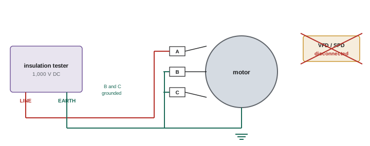
Before testing, the circuit must be de-energized, locked out and isolated: disconnect or bypass electronic equipment such as drives, surge protectors, metering, controls and LED drivers, which can be damaged by the test voltage or give false readings; open switches and remove loads so that only the conductors and equipment under test are connected. Test each phase to ground with the other phases grounded, and phase to phase, as appropriate. After testing, discharge the circuit for at least as long as the test voltage was applied, because long cables and large windings store significant charge.
Interpreting insulation resistance
Insulation resistance values depend strongly on temperature, humidity, cleanliness, conductor length and the type of insulation, so absolute numbers must be interpreted with care. Useful principles include:
- Longer cables have lower insulation resistance, because their leakage paths are in parallel; IR is roughly inversely proportional to length.
- Insulation resistance roughly halves for every 10 °C rise in temperature, so readings should be corrected to a standard base temperature, commonly 40 °C for rotating machines (IEEE 43) or 20 °C for cables, before comparison.
- Moisture and contamination lower readings dramatically; a motor that has stood idle in a damp area may read low but recover after drying.
- Trends are more informative than single values: a steady decline over several annual tests indicates deterioration even if each reading is above the minimum.
IEEE 43 recommends minimum insulation resistance for motor windings at 40 °C of about 100 MΩ for most form-wound and modern random-wound machines rated below 1 kV, and 5 MΩ for random-wound machines below 1 kV with older insulation systems, with higher values for higher-voltage machines.
Worked problem
Temperature-correcting a motor reading
A 460 V motor winding measures 60 MΩ at 20 °C. Correct to 40 °C and compare with a 100 MΩ minimum.
Show solution
- KT = 0.5^((40 − 20)/10) = 0.5² = 0.25.
- R40 = 0.25 × 60 = 15 MΩ.
- At the 40 °C reference, the winding is well below 100 MΩ.
- Investigate: check for moisture or contamination, perform a polarization index test, and consider cleaning and drying before energizing.
- Record the corrected value for trending.
Answer: About 15 MΩ at 40 °C, below the 100 MΩ guideline; investigate before energizing.
Time-resistance tests: DAR and PI
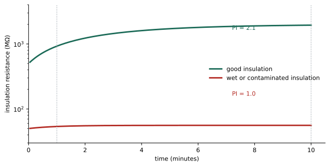
When a DC voltage is applied to insulation, the current decreases over time as the insulation polarizes. Clean, dry insulation shows resistance rising steadily over several minutes; wet or contaminated insulation shows little rise because leakage current dominates. Time-resistance tests use this behaviour, largely independent of temperature, to judge condition:
- Dielectric absorption ratio (DAR): resistance at 60 seconds divided by resistance at 30 seconds. Values above about 1.4 indicate good insulation; below about 1.25 are questionable.
- Polarization index (PI): resistance at 10 minutes divided by resistance at 1 minute. IEEE 43 recommends a minimum PI of 2.0 for class B, F and H insulation; values below 1.0 indicate serious problems. Modern insulation systems with very high resistance (above 5,000 MΩ) may show low PI values that are not meaningful, so the absolute value is also considered.
Other insulation tests
Several other tests assess insulation more deeply. Step voltage tests apply increasing test voltages and look for resistance falling as voltage rises, which indicates cracks or weak spots. High-potential (hipot) tests apply a voltage above the operating level, AC or DC, for a set time to prove insulation can withstand stress, used in acceptance testing of switchgear and cables. Very low frequency (VLF) testing, at 0.1 Hz, is preferred for medium-voltage cables with polymeric insulation because high DC voltages can damage them. Partial discharge testing and tan delta (dissipation factor) testing measure insulation quality in medium- and high-voltage equipment and are covered in Lesson 11. Surge testing of motor windings detects turn-to-turn insulation faults that IR testing cannot see, because IR testing only checks insulation to ground.
Testing in practice
Good practice for insulation testing includes: verify isolation and lockout; disconnect sensitive equipment; record ambient temperature, humidity and equipment temperature; use consistent test voltages and durations so results can be compared; guard the test area so no one touches conductors under test; discharge fully afterwards; and record results with instrument serial numbers. When readings are low, isolate sections of the circuit to locate the problem: disconnect the motor from its cable and test each separately, or split a long feeder at junction points. Many apparent insulation failures turn out to be a forgotten connected device, such as a surge protector, an indicator light or a heater, which is why carefully reviewing what is connected comes first.
Testing cables and feeders before energization
On new installations, insulation testing of every feeder and branch circuit before energization catches damage that occurred during pulling, nicks from staples or knockouts, conductors pinched under covers and wiring errors such as a neutral connected to a phase terminal. A typical procedure is to test each conductor to every other conductor and to ground with loads and devices disconnected, at 500 V for 120/240 V and 120/208 V circuits and 1,000 V for 347/600 V or 277/480 V circuits, unless specifications state otherwise. For multi-conductor cables and cables in shared raceways, testing between all conductors is important because damage often affects adjacent conductors together. Results are recorded on a cable test schedule, with low readings investigated by testing sections of the run. Combining these tests with continuity and polarity checks gives strong assurance that circuits are ready to energize safely.
Factors that influence readings
When readings seem inconsistent, consider external factors. Surface leakage across dirty or damp terminal blocks, insulators and cable ends can lower readings significantly; many insulation testers have a guard terminal that bypasses surface leakage so only current through the insulation itself is measured. High humidity causes condensation on cold equipment. Long test leads lying across wet floors add their own leakage. And capacitance of long cables means readings take time to stabilize, so always record readings at a consistent time, such as one minute, for comparison. Understanding these factors avoids condemning good equipment or passing bad equipment.
Safety during insulation testing
Insulation testing introduces its own hazards. The test voltage, up to several thousand volts, can cause shocks and, on circuits with significant capacitance, the stored charge can be lethal after the test ends. Before testing, confirm that no one is working on any part of the circuit, including at remote ends of cables, and post barriers or a person at the far end. Never touch test leads or conductors during the test. After testing, allow the instrument's automatic discharge to complete, then apply a discharge stick or grounding lead for at least as long as the test lasted, longer for large motors and long cables, and verify zero voltage. Remember that insulation testing is performed on locked-out equipment, so the normal lockout procedure applies, with the tester treated as an additional energy source under the tester's control.
Interpreting phase-to-phase and phase-to-ground results together
Comparing several readings helps locate problems. If one phase reads low to ground while the others are high, the fault is in that phase's insulation or a device connected to it. If two phases read low to each other but normal to ground, the problem is between them, such as moisture in a shared splice or damage where conductors are pressed together. If all readings are uniformly low, suspect general moisture, contamination, or a connected device such as a surge protector or control transformer that should have been disconnected.
Insulation and continuity tests are also valuable after repairs. Any time a cable is spliced, a motor is rewound, or equipment is reconnected after maintenance, repeating these tests before re-energizing confirms that the work was done correctly and that no damage was introduced, closing the loop between troubleshooting and verification.
Common mistakes
MistakeTesting insulation with drives and surge protectors connected.
InsteadDisconnect electronics and isolate the circuit first.
MistakeComparing readings taken at different temperatures.
InsteadCorrect to a base temperature before comparison.
MistakeRelying on a continuity beep for bonding.
InsteadMeasure resistance and compare with expected values.
MistakeTouching conductors right after an IR test.
InsteadDischarge for at least the test duration.
MistakeJudging insulation on one reading.
InsteadUse PI or DAR and trend results over time.
Summary and key terms
- Continuity testing confirms low-resistance connections; insulation testing confirms separation.
- Compare measured resistance with values estimated from conductor size and length.
- IR tests use DC voltages chosen by equipment rating.
- Isolate electronics, test phase to ground and phase to phase, then discharge.
- IR halves roughly every 10 °C; correct readings to a base temperature.
- DAR and PI assess insulation condition from resistance rise over time.
- Hipot, VLF, step voltage and surge tests examine insulation further.
- Continuity
- An unbroken, low-resistance electrical path.
- Micro-ohmmeter
- Instrument measuring very low resistances with high current.
- Insulation resistance
- Resistance of insulation to leakage current.
- Megohm
- One million ohms.
- Temperature correction
- Adjusting IR to a reference temperature.
- DAR
- Dielectric absorption ratio, 60 s over 30 s readings.
- Polarization index
- Ratio of 10-minute to 1-minute IR.
- Hipot test
- Overvoltage withstand test of insulation.
- VLF test
- Very low frequency AC test for MV cables.
- Surge test
- Test detecting turn-to-turn winding faults.
Practice problems
Work each problem on paper first, then reveal the answer to check.
What does continuity testing confirm?
Show answer
Conductors are connected with low resistance.
Expected resistance of 50 m of 14 AWG copper at 8.3 Ω/km?
Show answer
About 0.42 Ω.
Typical IR test voltage for 600 V equipment?
Show answer
1,000 V DC.
Why disconnect drives before IR testing?
Show answer
They can be damaged and distort readings.
How does cable length affect IR?
Show answer
Longer cables read lower.
Correct 200 MΩ at 30 °C to 40 °C.
Show answer
100 MΩ.
Define PI.
Show answer
10-minute resistance divided by 1-minute resistance.
Minimum PI per IEEE 43 for class F insulation?
Show answer
2.0.
Which test finds turn-to-turn faults?
Show answer
Surge test.
Why discharge after testing?
Show answer
Cables and windings store dangerous charge.
Lesson quiz · 5 questions
Score 60% or more to complete this lesson.
Create a free account to save your progress, take quizzes and earn a certificate.