
ELE-210 · Lesson 9 of 12 · 21 min
Registers and counters
One flip-flop stores one bit. Put several flip-flops side by side on the same clock and they store a word: that is a register. Connect the flip-flops so that each passes its value to the next and they form a shift register. Add logic that computes the next value from the present one and the register becomes a counter. Registers and counters are the workhorses of sequential design. They hold data in processors, convert between serial and parallel data on communication links, divide clock frequencies, measure time intervals and count events. This lesson covers each kind and finishes the counting chain of Cedarline's tachometer.
Registers
An n-bit register is n D flip-flops sharing a clock. At each rising edge, every flip-flop loads its own D input, so the whole word is captured at once. Most registers also need to hold their value on most clock cycles and load only when told to. This is done with a load enable: a 2-to-1 multiplexer in front of each D input chooses between the new data (when LOAD = 1) and the flip-flop's own output (when LOAD = 0). It is tempting to gate the clock instead, turning it off when the register should hold, but gating the clock with ordinary logic adds delay and glitches to the clock path and causes timing problems. In synchronous design the clock goes to every flip-flop untouched and enables are handled in the data path.
Register files, the small fast memories inside processors, are arrays of such registers with decoders selecting which one to write and multiplexers selecting which ones to read. The tachometer uses simpler registers: one holds the last complete count so that the display can show it steadily while the counter starts again, and one holds the overspeed limit.
Shift registers
In a shift register, the output of each flip-flop feeds the D input of the next, so at every clock edge the stored bits move one place along. A new bit enters at one end through the serial input and the bit at the other end leaves through the serial output. Shift registers come in four classic configurations, named by how data goes in and out: serial-in serial-out (a delay line), serial-in parallel-out (SIPO), parallel-in serial-out (PISO) and parallel-in parallel-out. A universal shift register can shift left, shift right, load in parallel or hold, chosen by two mode bits that drive a 4-to-1 mux in front of each flip-flop.
Shift registers convert between serial and parallel data, which is how almost every communication link works. A UART, an SPI port, USB and Ethernet all send bits one at a time over a wire and use shift registers at each end to turn words into bit streams and back. They also expand outputs cheaply: a SIPO shift register lets a microcontroller drive eight or more LEDs from three pins. Shifting left by one place multiplies an unsigned number by two and shifting right divides by two, so shift registers also appear in arithmetic circuits.
Ring and Johnson counters
A shift register whose serial output is fed back to its serial input circulates its contents. Loaded with a single 1, an n-bit ring counter passes the 1 around and has n states, with exactly one output high in each, which makes it a ready-made sequencer for n steps. A Johnson counter, or twisted-ring counter, feeds back the complement of the last output instead. An n-bit Johnson counter has 2n states, each differing from the next in one bit, and any state can be decoded with a single 2-input gate. Both waste states compared with binary counting, but their outputs are glitch-free and easy to decode. Both also need care at start-up: a ring counter that powers up with all 0s or with two 1s will circulate the wrong pattern forever unless the design forces a valid state.
Asynchronous (ripple) counters
The simplest binary counter chains T flip-flops with T = 1, each clocked by the output of the one before. The first flip-flop toggles on every clock edge, the second toggles every time the first goes from 1 to 0, and so on, so the outputs count in binary. With n flip-flops the counter divides the input frequency by 2ⁿ. This ripple counter uses very little logic, but each flip-flop changes only after the one before it, so the delay accumulates. During the transition from 0111 to 1000, the outputs pass briefly through 0110, 0100 and 0000. Logic that decodes those outputs will see these false states as glitches. Ripple counters are still used as frequency dividers where only the final output matters, but not where the count is decoded.
Synchronous counters
In a synchronous counter every flip-flop shares the same clock, so all the bits change together after one clock-to-output delay. The next-state logic decides which bits toggle. In binary counting, bit i toggles exactly when all lower bits are 1. With T flip-flops, T₀ = 1, T₁ = Q₀, T₂ = Q₁Q₀, T₃ = Q₂Q₁Q₀ and so on. With D flip-flops, which is how modern tools build them, the next state is simply the present count plus one, so a synchronous counter is a register whose input comes from an incrementer: a chain of half adders.
Practical counters add control inputs: an enable (count only when EN = 1), a synchronous clear, a parallel load to start from any value, and an up/down input. A terminal count output, active when the counter reaches its last state with the enable on, lets counters be chained: the terminal count of one stage enables the next, giving a wider counter that is still fully synchronous.
Modulo-N counters
A counter that cycles through N states instead of 2ⁿ is a modulo-N, or divide-by-N, counter. The most common is the decade counter, which counts 0 to 9 and then returns to 0, giving one BCD digit. The clean synchronous way to build one is to detect the last state and force a synchronous clear (or load) at the next edge: when the count is 9 and the counter is enabled, the next state is 0. Detecting state 9 in a 4-bit counter needs only Q₃ and Q₀, because 9 is the only state from 0 to 9 with both bits set. An asynchronous clear driven by decoding state 10 also works on paper, but it produces a brief spike of the state 10 and depends on the race between the reset and the decoding logic, so it is avoided in good designs.
Worked problem
Decade counter next-state logic
Design the next-state logic for a synchronous decade counter built from D flip-flops, with states 0000 to 1001.
Show solution
- For states 0 to 8, the next state is the present state plus 1. In state 9 (1001) the next state is 0000. States 10 to 15 never occur, but Amara checks that the logic leads each of them back to a legal state rather than trapping the counter.
- Write the next-state table and minimize each bit with K-maps, using Q₃Q₂Q₁Q₀.
- \[D_0 = \overline{Q_0}\]
- \[D_1 = \overline{Q_3}(Q_1 \oplus Q_0)\]
- \[D_2 = \overline{Q_3}\,(Q_2 \oplus Q_1Q_0)\]
- \[D_3 = \overline{Q_3}\,Q_2Q_1Q_0 + Q_3\overline{Q_2}\,\overline{Q_1}\,\overline{Q_0}\]
- Check state 9 (1001): D₀ = 0, D₁ = 0, D₂ = 0, D₃ = 0, so the next state is 0000.
- Check the illegal states: 10, 12 and 14 go to 0001 and 11, 13 and 15 go to 0000, so a counter upset into an illegal state recovers on the next clock.
Answer: The counter counts 0 to 9 and wraps to 0, and every illegal state returns to a legal state in one clock.
The equation for D₃ deserves a second look. Its first term handles the step from 7 to 8. Its second term keeps Q₃ set when moving from 8 to 9. In every other state, including 9 and the illegal states, D₃ = 0. Chaining four decade counters gives a counter from 0000 to 9999 in BCD, ready to drive the display without any conversion.
Counters as timers and frequency dividers
A counter clocked by a known frequency measures time. A 1 MHz clock driving a counter that wraps at 50,000 produces a pulse every 50 ms. Dividing a fast crystal oscillator down to slower clocks or tick signals is one of the most common uses of counters. Cedarline's controller runs from a 1 MHz clock and uses a divide-by-1,000 counter to produce a 1 ms tick, which drives the 20 ms debounce timer for the pedestrian button and the timers that hold each traffic light for its programmed time.
The tachometer counting chain
The tachometer measures shaft speed by counting sensor pulses over a fixed gate time. The shaft has a toothed wheel with 60 teeth, so the sensor gives 60 pulses per revolution. A gate counter divides the 1 MHz clock to make a 1 s gate signal. During each gate period, a 4-digit BCD pulse counter counts the sensor pulses, after they have been cleaned up and synchronized to the clock. At the end of the gate, the count is loaded into a display register and the pulse counter is cleared for the next period. Because the wheel has 60 teeth and the gate is 1 s, the count equals the shaft speed in revolutions per minute directly.
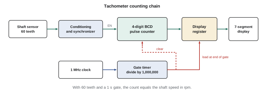
Lesson 1 sized the counter at 10 bits for a binary count up to 1,000. In BCD, four decade counters cover 0 to 9,999 rpm. The resolution is 1 rpm with a 1 s gate. A shorter gate updates the display faster but coarsens the resolution: with a 0.1 s gate, each count is 10 rpm. At low speeds, measuring the period between pulses gives better resolution than counting them, and many tachometers switch between the two methods.
# Tachometer: count pulses in a gate time, with a BCD decade-counter chain
TEETH, GATE_S = 60, 1.0

def bcd_count(pulses, digits=4):
    d = [0] * digits                 # d[0] is the units digit
    for _ in range(pulses):
        i = 0
        while i < digits:            # ripple the decimal carry through enabled stages
            d[i] += 1
            if d[i] < 10:
                break
            d[i] = 0
            i += 1
    return "".join(str(x) for x in reversed(d))

for rpm in (35, 1450, 2999, 10500):
    pulses = round(rpm / 60 * TEETH * GATE_S)
    shown = bcd_count(pulses)
    note = "  <-- overflow, the display wrapped" if pulses > 9999 else ""
    print(f"shaft {rpm:5d} rpm -> {pulses:5d} pulses -> display {shown}{note}")
print("resolution with a 0.1 s gate:", 60 / (TEETH * 0.1), "rpm per count")shaft 35 rpm -> 35 pulses -> display 0035 shaft 1450 rpm -> 1450 pulses -> display 1450 shaft 2999 rpm -> 2999 pulses -> display 2999 shaft 10500 rpm -> 10500 pulses -> display 0500 <-- overflow, the display wrapped resolution with a 0.1 s gate: 10.0 rpm per count
The last case is a reminder from lesson 1: fixed-width counters wrap around. Amara adds an overflow flip-flop, set by the terminal count of the top digit, that lights an over-range indicator, because a tachometer that silently reads 500 rpm when the shaft is turning at 10,500 rpm is dangerous.
Linear feedback shift registers
A linear feedback shift register (LFSR) is a shift register whose serial input is the XOR of a few chosen outputs, called taps. With the right taps, an n-bit LFSR steps through all 2ⁿ − 1 non-zero states in a fixed but scrambled order before repeating. LFSRs generate pseudo-random test patterns, scramble data on communication links, compute CRC check values (lesson 2), and make very fast counters, since the next-state logic is a single XOR gate. The all-zero state must be avoided, because zeros XORed together stay zero forever.
# A 4-bit maximal-length LFSR (taps on bits 3 and 2, x^4 + x^3 + 1)
state, seen = 0b0001, []
for _ in range(16):
    seen.append(state)
    feedback = ((state >> 3) ^ (state >> 2)) & 1
    state = ((state << 1) | feedback) & 0b1111
    if state == seen[0]:
        break
print("period:", len(seen))
print(" ".join(f"{s:04b}" for s in seen))period: 15 0001 0010 0100 1001 0011 0110 1101 1010 0101 1011 0111 1111 1110 1100 1000
Common mistakes
MistakeGating the clock to make a register hold.
InsteadKeep the clock untouched and use a load-enable multiplexer in the data path.
MistakeDecoding the outputs of a ripple counter.
InsteadRipple counters pass through false states; use a synchronous counter when outputs are decoded.
MistakeResetting a modulo-N counter asynchronously when it reaches N.
InsteadDetect state N − 1 and load 0 synchronously at the next edge.
MistakeAssuming ring, Johnson and LFSR counters always start in a valid state.
InsteadForce a valid state at reset; illegal states may otherwise circulate forever.
MistakeIgnoring counter overflow in a measurement.
InsteadAdd a terminal-count flag or more digits so that over-range readings are flagged.
Summary and key terms
- A register is a group of D flip-flops on one clock; a load-enable mux makes it hold or load.
- Shift registers move bits one place per clock and convert between serial and parallel data.
- Ring counters have n states with one hot bit; Johnson counters have 2n states and glitch-free decoding.
- Ripple counters are simple dividers but pass through false states; synchronous counters change all bits together.
- A modulo-N counter detects its last state and clears or loads synchronously.
- Counters measure time and frequency; an LFSR cycles through 2ⁿ − 1 states with XOR feedback.
- Register
- A group of flip-flops that store a word on a common clock.
- Load enable
- A control input that makes a register take new data; otherwise it keeps its value.
- Shift register
- A chain of flip-flops in which each passes its value to the next on every clock edge.
- Synchronous counter
- A counter whose flip-flops share one clock, so all bits change together.
- Modulo-N counter
- A counter that cycles through N states.
- Terminal count
- An output that is active in a counter's last state, used to chain counters.
- LFSR
- Linear feedback shift register: a shift register with XOR feedback that cycles through a long pseudo-random sequence.
Practice problems
Work each problem on paper first, then reveal the answer to check.
How many flip-flops does a ring counter need for a 6-step sequence? A Johnson counter?
Show answer
Six for a ring counter; three for a Johnson counter (2 × 3 = 6 states).
A 4-bit ripple counter is clocked at 16 MHz. What frequency appears at the MSB?
Show answer
16 MHz / 16 = 1 MHz.
Write T₃ for a synchronous 4-bit up counter with enable EN.
Show answer
T₃ = EN·Q₂Q₁Q₀.
Which state does a decade counter detect to wrap to 0, and which bits are enough to detect it?
Show answer
State 9 (1001); Q₃ and Q₀ are enough among legal states.
A tachometer wheel has 30 teeth and the gate time is 2 s. What count corresponds to 1,200 rpm?
Show answer
1,200/60 × 30 × 2 = 1,200 pulses.
A divide-by-N counter makes a 1 ms tick from a 25 MHz clock. What is N?
Show answer
N = 25,000.
Lesson quiz · 5 questions
Score 60% or more to complete this lesson.
Create a free account to save your progress, take quizzes and earn a certificate.