
ELE-210 · Lesson 11 of 12 · 26 min
Timing and clocking
Boolean algebra treats signals as if they changed instantly. Real gates and wires take time, and a sequential circuit works only if every signal arrives where it is needed, settled, before the clock edge that captures it, and does not change too soon after. Timing is where most real design problems hide. A circuit that is logically perfect can fail at full speed, fail only when it is hot, or fail once a week when an asynchronous input happens to change at an unlucky instant. This lesson covers propagation and contamination delay, setup and hold times, the maximum clock frequency, clock skew, glitches and hazards, metastability and synchronizers, and signals that cross between clock domains.
Propagation and contamination delay
Lesson 4 defined a gate's propagation delay, tpd, as the longest time from an input change to the output settling at its new value. Timing analysis also needs the opposite bound: the contamination delay, tcd, is the shortest time from an input change until the output starts to change. Between the two, the output may be changing and its value cannot be trusted. Delays vary with the manufacturing process, the supply voltage and the temperature, so datasheets and timing libraries give minimum and maximum values, and a design must work across the whole range.
The propagation delay of a path through several gates is the sum of the gate delays along it, plus wire delays. The critical path is the slowest path from any input or flip-flop output to any output or flip-flop input, and it sets the speed of the circuit. The shortest path, found with contamination delays, matters too, as hold time analysis shows below.
Worked problem
Critical path through the walk-request logic
W = PM̄ + T is built from an inverter (tpd = 0.10 ns, tcd = 0.05 ns), a 2-input AND (tpd = 0.15 ns, tcd = 0.08 ns) and a 2-input OR (tpd = 0.15 ns, tcd = 0.08 ns). Find the propagation and contamination delays from the inputs to W.
Show solution
- Path from M: inverter, AND, OR: =0.10 + 0.15 + 0.15 = 0.40\ \text{ns}
- Path from P: AND, OR: 0.30 ns. Path from T: OR only: 0.15 ns.
- The propagation delay is the longest path, 0.40 ns, through the inverter.
- The contamination delay is the shortest path, from T through the OR: tcd = 0.08 ns.
Answer: tpd = 0.40 ns (critical path from M) and tcd = 0.08 ns (from T).
Flip-flop timing parameters
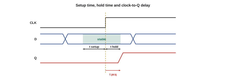
A flip-flop has three key timing numbers. The setup time, tsetup, is how long D must be stable before the clock edge. The hold time, thold, is how long D must stay stable after the edge. The clock-to-Q delay, tpcq, is how long after the edge the output Q settles at its new value, with a corresponding minimum, the contamination clock-to-Q delay tccq. If D changes inside the window from tsetup before the edge to thold after it, the flip-flop may capture the wrong value or become metastable.
Setup time and the maximum clock frequency
Consider two flip-flops with combinational logic between them, both on the same clock. At a rising edge, the first flip-flop launches new data, which appears at its output after tpcq, travels through the logic in up to tpd, and must arrive at the second flip-flop at least tsetup before the next rising edge. The clock period Tc must therefore be at least the sum of these three delays. The slowest such path in the design sets the maximum clock frequency.
If a design misses its target frequency, the designer shortens the critical path: by simplifying logic, by using a faster structure such as a carry-lookahead adder, or by pipelining, which splits a long path into stages with registers between them. Pipelining lets the clock run faster at the cost of more registers and a few cycles of latency, and it is used throughout processors and signal-processing chips.
Hold time and short paths
The hold constraint concerns the fastest path. At the same clock edge that captures data in the second flip-flop, the first flip-flop launches new data. If that new data races through a very short path and reaches the second flip-flop before its hold time has ended, it corrupts the value being captured. The earliest arrival is tccq + tcd, and it must be at least thold. Unlike setup violations, hold violations cannot be fixed by slowing the clock, because both events happen at the same edge. They are fixed by adding delay to the short path, usually buffers inserted by the layout tools.
Flip-flops are designed so that tccq is greater than thold, so two flip-flops connected directly, with no logic between them, satisfy hold without help. This is what makes shift registers work. Hold problems appear mainly when clock skew is large.
Clock skew
The clock does not reach every flip-flop at exactly the same moment, because the wires and buffers that distribute it have different delays. The difference in arrival time between two flip-flops is clock skew. Skew eats into the margins: if the capturing flip-flop's clock arrives earlier than the launching one's, the setup budget shrinks; if it arrives later, the hold budget shrinks. Chip designers build balanced clock trees and grids to keep skew small, and timing tools include the skew in every check. Clock jitter, the variation of each edge from its ideal time, has a similar effect on setup margins.
# Setup and hold checks for a register-to-register path (all times in ns)
t_pcq, t_ccq = 0.30, 0.10          # clock-to-Q, maximum and minimum
t_setup, t_hold = 0.20, 0.05
paths = {"adder carry chain": (4.10, 0.40), "state decode": (1.20, 0.25), "direct shift": (0.00, 0.00)}

for skew in (0.0, 0.15):
    worst = max(t_pcq + tpd + t_setup + skew for tpd, _ in paths.values())
    print(f"skew {skew:.2f} ns: minimum period {worst:.2f} ns, f_max {1000 / worst:.0f} MHz")
    for name, (tpd, tcd) in paths.items():
        slack_hold = t_ccq + tcd - (t_hold + skew)
        flag = "ok" if slack_hold >= 0 else "HOLD VIOLATION - add delay"
print(f" {name:18s} hold slack {slack_hold:+.2f} ns {flag}")skew 0.00 ns: minimum period 4.60 ns, f_max 217 MHz adder carry chain hold slack +0.45 ns ok state decode hold slack +0.30 ns ok direct shift hold slack +0.05 ns ok skew 0.15 ns: minimum period 4.75 ns, f_max 211 MHz adder carry chain hold slack +0.30 ns ok state decode hold slack +0.15 ns ok direct shift hold slack -0.10 ns HOLD VIOLATION - add delay
The result shows both effects. With no skew, the adder path limits the clock to about 217 MHz and every path meets hold. With 0.15 ns of skew in the unfavourable direction, the maximum frequency drops, and the direct connection of a shift register fails hold, which no change of clock frequency can fix. Static timing analysis tools perform these checks on every path in a design, millions of them in a large chip, using worst-case delays for setup and best-case delays for hold.
Glitches and hazards
Because different paths through combinational logic have different delays, an output can briefly take a wrong value while the inputs change, even when the final value is correct. Such a short unwanted pulse is a glitch. A static-1 hazard occurs when the output should stay at 1 but momentarily drops to 0; a static-0 hazard is the reverse; a dynamic hazard is an output that should change once but bounces several times. In a two-level sum of products, a static-1 hazard happens when a single input change moves from one product term to another and the two terms are not both covered by a third term during the change.
Worked problem
Removing a static-1 hazard
F = AB + ĀC. With B = C = 1, F should stay 1 when A changes, but the AND gate fed by Ā is slower because of the inverter. Show the hazard and remove it.
Show solution
- With B = C = 1, F = A + Ā = 1 logically.
- When A falls from 1 to 0, the term AB turns off at once, but ĀC turns on only after the inverter delay. For a moment both terms are 0, and F glitches to 0.
- On the K-map, the two groups AB and ĀC are adjacent but do not overlap. Adding the consensus term BC covers the transition.
- \[F = AB + \overline{A}C + BC\]
Answer: Adding the redundant consensus term BC keeps F at 1 during the change: BC = 1 throughout.
Lesson 3 noted that the consensus term is logically redundant. Here it earns its place. In synchronous design, though, glitches in combinational logic usually do not matter, because flip-flops sample the logic outputs only after everything has settled, which is exactly what the setup constraint guarantees. Glitches matter when a combinational output drives something that reacts immediately: an asynchronous reset, a clock input, a latch enable or an external device. This is another reason the clock and asynchronous resets of a synchronous design must never be driven by ordinary combinational logic.
Metastability and synchronizers
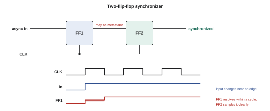
Some inputs are not synchronized to the clock at all. The pedestrian button, the car sensor and data from another system with its own clock can change at any instant, so sooner or later one will change inside a flip-flop's setup and hold window. Lesson 8 described what can happen: the flip-flop may go metastable and take an unpredictable time to resolve to 0 or 1. If the logic it feeds reads the output while it is still unresolved, different parts of the logic may see different values, which can send a state machine into an impossible state.
The standard cure is a synchronizer: pass the asynchronous signal through two (or for very fast clocks, three) flip-flops in series on the destination clock, and use only the output of the last one. If the first flip-flop goes metastable, it has almost a full clock period to resolve before the second flip-flop samples it. The probability of failure falls exponentially with the time allowed for resolution, so one extra stage makes the mean time between failures enormous.
Here tr is the time available for resolution (roughly one clock period minus the setup time and clock-to-Q delay), τ is a time constant of the flip-flop, typically tens of picoseconds in modern technology, T₀ is a technology constant giving the width of the vulnerable window, and fclk and fdata are the clock frequency and the rate at which the asynchronous input changes.
# Mean time between synchronizer failures, one flip-flop versus two
import math
f_clk, f_data = 1e6, 10.0          # 1 MHz controller clock; inputs change about 10 times a second
tau, T0 = 50e-12, 20e-12           # illustrative flip-flop constants
overhead = 0.5e-9                  # clock-to-Q plus setup of the next stage
T = 1 / f_clk
cases = {"1 flip-flop, 0.1 ns of slack": 0.1e-9,
         "2 flip-flops": T - overhead}
for name, t_r in cases.items():
    log10_mtbf = t_r / tau / math.log(10) - math.log10(T0 * f_clk * f_data)
    if log10_mtbf < 6:
        print(f"{name:30s} resolution {t_r * 1e9:7.1f} ns  MTBF about {10 ** log10_mtbf / 3600:.0f} hours")
    else:
print(f"{name:30s} resolution {t_r * 1e9:7.1f} ns MTBF about 10^{log10_mtbf:,.0f} s")1 flip-flop, 0.1 ns of slack resolution 0.1 ns MTBF about 10 hours 2 flip-flops resolution 999.5 ns MTBF about 10^8,685 s
The numbers are dramatic because the exponent grows with the resolution time. With almost no slack, a single flip-flop driving logic directly fails about every ten hours. With a second stage and a microsecond to resolve, the mean time between failures exceeds the age of the universe by a vast margin. Fast chips running at gigahertz rates have much less time per stage, so their synchronizers use three stages and flip-flops designed for small τ. Amara's controller synchronizes the button, the car sensor, the emergency pre-emption input and the remote test input, each through its own two-flip-flop synchronizer, before anything else looks at them.
Crossing clock domains
Large systems often have several clocks: a fast one for processing, a slow one for a display, another for a communication link. A signal passing from one clock domain to another is effectively asynchronous to the receiving clock and must be synchronized. A single control bit can use a two-flip-flop synchronizer, but a multi-bit value cannot simply be synchronized bit by bit, because the bits may be captured on different cycles and combine into a value that never existed. Three common techniques solve this. A handshake sends a request signal, waits for a synchronized acknowledgement, and only then changes the data. An asynchronous FIFO buffers data between the domains and passes its read and write pointers across in Gray code, so that only one bit changes at a time and a misread pointer is off by at most one. A pulse synchronizer converts a one-cycle pulse into a level change that the other side can safely detect. Crossing clock domains correctly is one of the subtler skills of digital design, and design tools include checks that look specifically for unsynchronized crossings.
Clocks and resets in practice
Clock quality matters. The clock comes from a crystal or a phase-locked loop, travels through a dedicated low-skew network, and must never be generated or gated by ordinary logic. When a design genuinely needs to turn a clock off to save power, it uses a special clock-gating cell built to produce no glitches. Resets need similar care. An asynchronous reset is convenient at power-up, but its release must be synchronized to the clock, using a reset synchronizer, so that all flip-flops leave reset on the same clock edge. Otherwise some flip-flops may leave reset one cycle before others and the state machine may start in a state that is not its reset state.
Common mistakes
MistakeFixing a hold violation by lowering the clock frequency.
InsteadHold depends only on short-path delays and skew; add delay to the fast path.
MistakeReading an asynchronous input with more than one flip-flop directly.
InsteadSynchronize it once through two flip-flops and use only the synchronized copy.
MistakeSynchronizing a multi-bit bus bit by bit.
InsteadUse a handshake, an asynchronous FIFO with Gray-coded pointers, or a single synchronized control bit.
MistakeDriving a clock or an asynchronous reset from combinational logic.
InsteadGlitches on these signals act immediately; use dedicated clock and reset circuits.
MistakeWorrying about glitches inside synchronous logic.
InsteadFlip-flops sample only after logic settles; glitches matter only where outputs act immediately.
Summary and key terms
- Propagation delay bounds the latest change of an output; contamination delay bounds the earliest.
- Setup: Tc ≥ tpcq + tpd + tsetup (+ skew) sets the maximum clock frequency.
- Hold: tccq + tcd ≥ thold (+ skew); hold violations are fixed by adding delay, not by slowing the clock.
- Clock skew and jitter reduce timing margins; static timing analysis checks every path.
- Hazards are glitches caused by unequal path delays; consensus terms remove static hazards in two-level logic.
- Asynchronous inputs need a two-flip-flop synchronizer; multi-bit clock-domain crossings need handshakes or Gray-coded FIFOs.
- Contamination delay
- The minimum time from an input change until an output begins to change.
- Critical path
- The slowest path through a circuit, which limits its clock frequency.
- Setup time
- The time before a clock edge during which a flip-flop's input must be stable.
- Hold time
- The time after a clock edge during which a flip-flop's input must remain stable.
- Clock skew
- The difference in clock arrival time between two flip-flops.
- Hazard
- A possible glitch in a combinational output caused by unequal path delays.
- Synchronizer
- A chain of flip-flops that reduces the probability of metastability reaching the rest of a design.
Practice problems
Work each problem on paper first, then reveal the answer to check.
A path has tpcq = 0.4 ns, tpd = 6.1 ns and tsetup = 0.5 ns. What is the maximum clock frequency?
Show answer
Tc = 7.0 ns, so fmax ≈ 143 MHz.
With tccq = 0.12 ns, tcd = 0 and thold = 0.08 ns, how much skew can a direct flip-flop connection tolerate?
Show answer
0.12 ≥ 0.08 + skew, so skew ≤ 0.04 ns.
Find the consensus term that removes the hazard in F = AC̄ + BC.
Show answer
AB.
Why does a second synchronizer flip-flop help so much?
Show answer
It gives the first flip-flop almost a full clock period to resolve, and failure probability falls exponentially with resolution time.
Why are FIFO pointers passed between clock domains in Gray code?
Show answer
Only one bit changes per increment, so a pointer sampled mid-change is off by at most one.
A design meets setup at 200 MHz but fails hold on one path. Will running at 100 MHz fix it?
Show answer
No; hold does not depend on the clock period. Add delay to the short path.
Lesson quiz · 5 questions
Score 60% or more to complete this lesson.
Create a free account to save your progress, take quizzes and earn a certificate.